Pag. 11
Technical Book
MDS
MDS
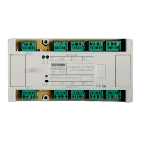
Relay decoder Ref. 2430
Provides relay outputs for alarm and automation purposes. Exclusively to work with MDS-Digital systems.
D
1
D2
26
NO
NC
C
C
N
O
N
C
C
NO N
O
NC
C
N
C
RELAYS DECODER
DECODER DE RELES
RELES / RELAYS
PGM
BUS
BUS
- V
FERMAX
REF. 2430
DECODER Nº:
M
A
D
E
IN
S
P
A
IN
5
1
3
2
6
7
4
8
REF. 2430
M
A
D
E
IN
S
P
A
IN
DECODER Nº
V
BUS
D
2
D
-
1
+
+
F
O
N
Sensor decoder Ref.2429
This decoder has been designed to work with MDS-Digital systems only
It has 8 sensor inputs that can be configured either to use N.O. (normally open) or N.C. (normally closed)
detectors by means of a jumper located beside each input. In both cases the activation signal can be sent
to the central unit immediately or delayed, depending on the "time" parameter that commands the alarm
signal.
Instant alarm: signal activation is sent to the central unit the moment that sensor activation is detected.
Bear in mind that the detection stays on as long as the sensor keeps detecting. The time parameter for this
function is "0".
Delayed alarm: signal activation is sent to central unit when the sensor has been activated for a pro-
grammed period of time (from 1 to 127 seconds or minutes)
"Time"and "sensor number" parameters are programmed into the decoder, and stay programmed even if
it is disconnected from the electric power. The "sensor number" can be programmed either from any
keypad with display or through a PC (by means of the Ref. 2466 module and the DecoWin software).
"Time" parameter is always programmed through a PC. See the "PC Programming Manual" for more
details.
D1
2
D2
6
S
-
S- S
-
-S
SENSORS DECODER
DECODER DE SENSORES
DECODER Nº:
5
BUS
BUS
M
A
D
E
IN
S
P
A
IN
FER
M
AX
R
EF. 2429
PGM
SEN
SO
R
ES / SEN
SO
R
S
2
6
1
78
3
4
C1
C2
Cn
C3
RELAY
DECODER
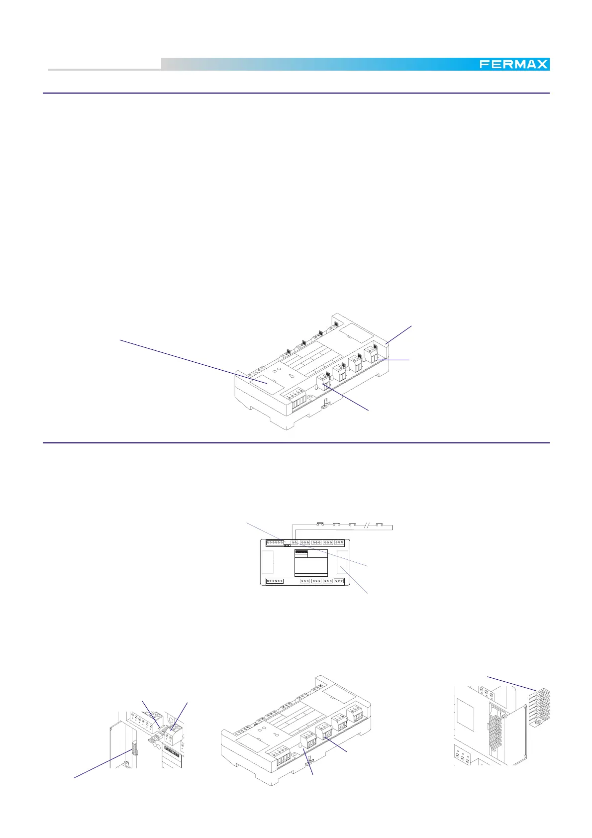
Jumper P1
CN-12 terminal.
If P1 is in ON then the loop in CN-12
has to be closed (Fire protection).
If P1 is in OFF, then the loop in CN-12
is not controlled.
TEST jumper
(under the cover)
For TEST jumpers be enable, P1 has to be
in ON.
It has 8 relay ouputs, which can be configured either as flip-flop (relay toggles in each activation) or as
timed mode (closing time for each relay can be set from 1 to 255 seconds). For "timed mode" a timer starts
to count the moment the relay is activated, releasing it once the time has expired.
Another interesting feature is the
FIRE ALARM facility.
This feature is achieved by means
of a connector (CN12), to connect
in series all the sensors we want
to use for detecting fire(forming a
loop connection), that would open
the loop when a fire alarm is gen-
erated somewhere. This signal would cause all the relays to be released in case of danger, for instance
allowing all the inhabitats to exit (releasing door locks controlled by the relays).
Max. current through the relay contacts: 2A (120-220V)
NC/NO sensors selector
PC Programming connector
under the cover
LED indicator
is ON when the connected sensor
is activated
PC Programming connector
P1
CN-12
LED indicator
is ON when the connected relay is activated
TEST jumpers. For checking
relay output. To be operative,
P1 has to be set in ON.
Relay output (8 units)
Sensor connector
8 units
 Loading...