Pag. 20
Technical Book
MDS
MDS
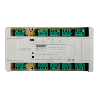
The link cable required is shown below. This cable is not included with the module.
6
5
4
3
2
1
7
8
9
PIN Nº: PIN Nº:
9
8
7
1
2
3
4
5
6
BROWN
RED
ORANGE
YELLOW
GREEN
MAX. 3m LENGTH
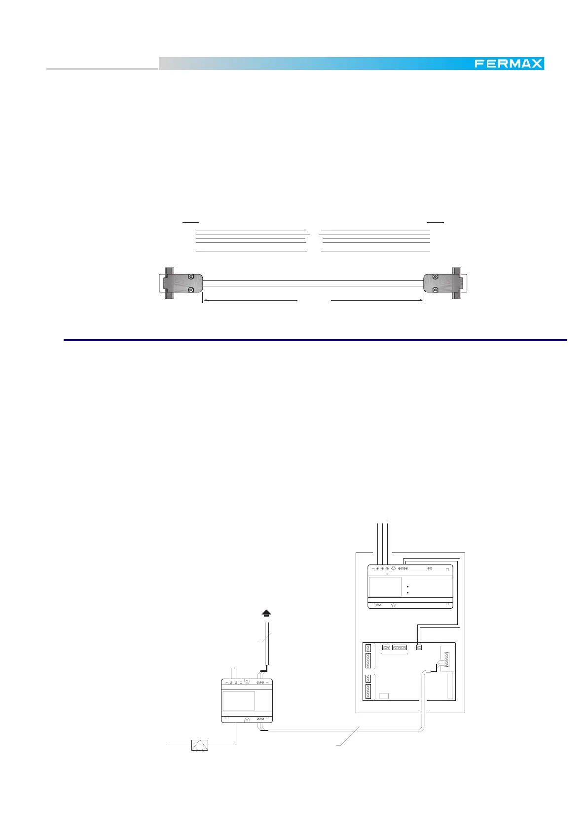
The figure shown on the previous page illustrates how to connect the FXL Programming Module Ref.2338
in a typical installation with 2 Central Units. For installations with more Central Units, the device may be
connected at any point between them (there is no restriction regarding the central units it is connected
between).
This device allows us to use a BASIC CITYMAX TELEPHONE REF.8044 for communication with any
outdoor panel or guard unit (see figure).
Remote Programming Module Ref. 2467
TELEPHONE LINE Shielded twisted pair
Shielded twisted pair
M.D.S. CENTRAL UNIT
Ref.2420
220 Vac
12V+ --+
REF. 8840
POWER SUPPLY
ALIMENTADOR
PRIM.
FE
+ - BAT.13.8V
A
B
G
A
B
G
NR-2067
NR-2055
DECODERS
PANEL 1 PANEL 0
12
-++-DD26CtVM
Ct
M
V
+
-
2
6
SA
SB
6
2
SB
SA
-
+
M
V
Ct
GESTION FXL-MODEM
MODEM FXL ACCESS
REF. 2467
RS-232 GBA
ABG
9-12 Vdc
TERMINAL
+-CFG
MODEM
FXL net
2338 Module side
PC side
It is also possible to connect to a MDS system remotely, via modem. Then all the same features are
available as with local connection. For this, a PC with the Wincom software connected to the telephone
line via Modem is required. The link cable between the PC and the modem is represented on the next page.
On the MDS side are required:
* Ref. 2467 Modem FXL Access Terminal
* Ref. 2428 FXL Network Card to connect the Ref. 2467 to a single MDS central Unit or to a FXL network.
* A 56K U.S. Robotics Modem to connect the Ref. 2467 to the telephone line.
* A link cable to connect the Ref. 2467 module to the modem (See next page). This cable is not included
with the module.
Use the MDS Wincom software from the remote PC to connect and program the MDS System, as if it were
connected directly to them. See instructions included with the Ref. 2427 PC Card for further details.
 Loading...