Pag. 28
Technical Book
MDS
MDS
MDS Swticher Module Ref. 2443
For MDS-CITY and MDS-DIRECT systems (or combinations). In Video installations the system requires one MDS
City/Direct Switcher Module Ref. 2443 for every additional panel, i.e.: an installation with 8 Video panels to the
same block would require seven MDS Switcher Modules.
REF.2443
MDS VIDEO SWITCHER PACK
PACK CAMBIADOR VIDEO MDS
VIDEO PLACA
PANEL VIDEO
S
V
VIDEO EXTERIOR
EXTERNAL VIDEO
Vi
SALIDA VIDEO
VIDEO OUTPUT
Vo
1
2
3
1. VIDEO-OUT to Monitors or next switcher.
2. VIDEO-IN 1 Incoming Video from Main Panel 1.
3. VIDEO-IN 2 Incoming Video from Panel 2.
5
LLAMADAS/CALLS
32 EXTENSION CALL PACK
REF.2442
PACK EXTENSION 32 LLAMADAS
SIGUIENTE/NEXT
ANTERIOR/PREVIOUS
16 EXTENSION CALL PACK
1
REF.2441
43276510981211 151413 16
PACK EXTENSION 16 LLAMADAS
SIGUIENTE/NEXT
ANTERIOR/PREVIOUS
LLAMADAS/CALLS
876
1
432 1091211 272625 28191817 20
313029 32232221 24151413 16
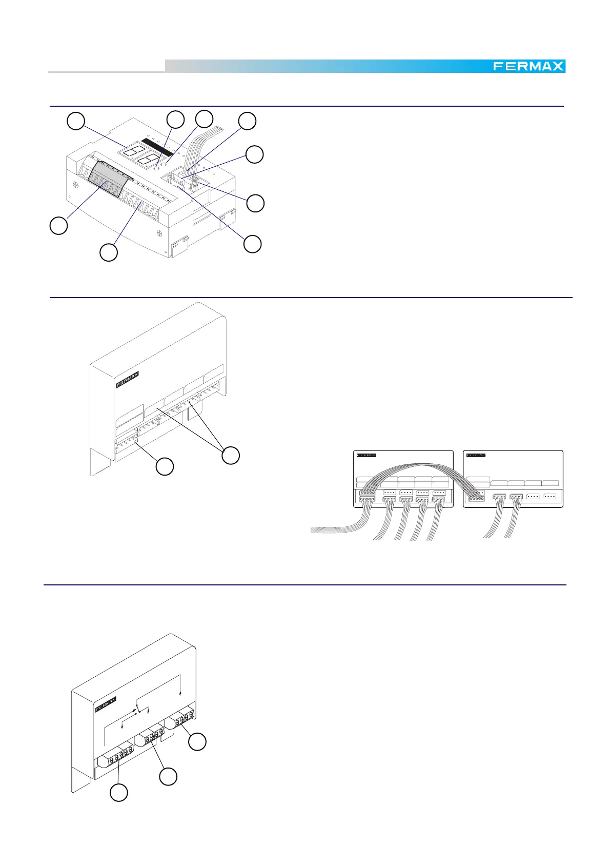
The 16- and 32-call Extension Packs (Ref. 2441 and Ref.2442
respectively) are necessary in MDS CITY Panels. They are
used as intermediaries between the normal City pushbuttons
and the MDS system.
In panels with more than 32 buttons, several interconnected
Packs must be used.
1. Links connector Connections to the Digitizer or to other Call
Extension Pack.
2. Call connectors Connections to the pushbuttons in panel.
Ct
1
2
FERMAX
S
P
+-
DD2662
2
1
+-
DD
+-
Digitizer Module Ref. 2440
Call Extension Pack Ref. 2441 & Ref. 2442
When several Call Extension Packs are linked to-
gether, the second one starts to count from the last
number in the previous one. In the example shown
right, the second Pack (on the right) controls
pushbuttons from 33 to 48.
ANTERIOR/PREVIOUS
REF.2441
43
SIGUIENTE/NEXT
2
1
PACK EXTENSION 16 LLAMADAS
16 EXTENSION CALL PACK
LLAMADAS/CALLS
6578 101191312 1614 15
2
1
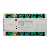
1. Input terminals. Connections from the MDS bus decoder of
the MDS Central Unit or from previous MDS DIRECT panels.
2. Information display. Shows the programming stage.
3. Select button. To select programming optgions
4. Programming button. To program the digitizer parameters.
5. PC link connector. To program the digitizer from a PC
6. Amplifier connector
7. J1. Allows direct contact from the panel with telephones in
(ON).
8. Call Extension module connector
9. Output terminals.Connections to the next panels or MDS Di-
rect/City or Decoders.
1
2
3
5
4
6
7
8
9
 Loading...