Pag. 7
Technical Book
MDS
MDS
DECODERS
These are the interface between the MDS BUS and the external devices (telephones, alarm sensors, etc.)
There is no limit to the number of decoders connected to an MDS system. The maximum number depends
on the devices connected. In any case, these specifications must be followed:
* Distance from the decoder to the telephone/monitor must always be less than 100 m.
* Maximum distance between the last decoder, and Outdoor Panel (or Central Unit), without repeaters
is 1.200 m.
* Maximum number of decoders without repeaters is 120.
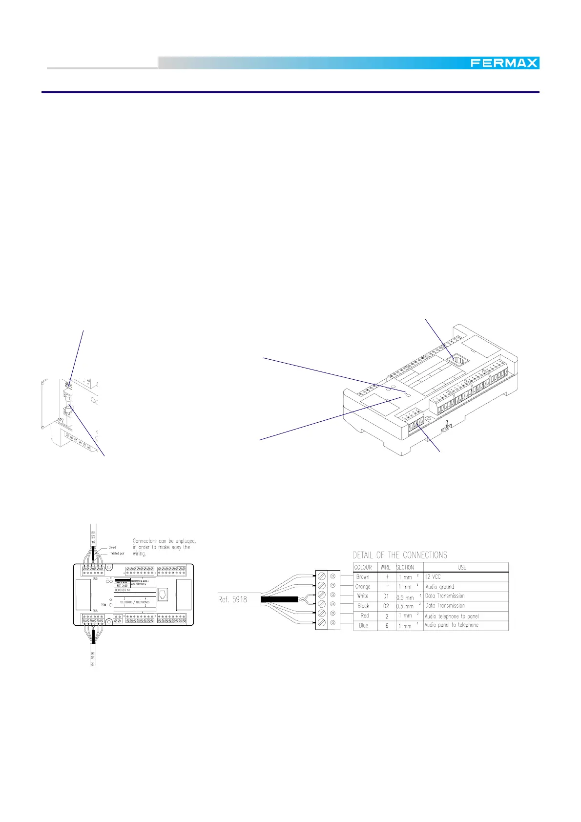
The MDS BUS is common for all types of decoders, independently of the decoder type. The connection
between the decoders and with the outdoor panel (or central unit) is by means of a bus consisting of 4
wires + 1 twisted pair (FERMAX cable REF.5918):
There are 7 different types of decoder to be used in the MDS systems.
Audio decoder 4. Used in standard installations. Provides connection for up to 4 telephones.
Audio decoder 8. The same as above, but providing connection for 8 telephones.
Audio Isodecoder 4. In addition to the audio decoder 4, provides total isolation of each telephone
from the rest of the installation (including the other telephones in the systems) and other panic calls.
Sensor decoder. Provides up to 8 alarm sensor inputs.
Relay decoder. Provides up to 8 relay contact outputs.
Panel decoder. Provides connection up to 4 standard 1 line City Panel.
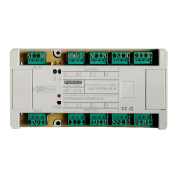
All of them have the same appearance, with some parts that are common to all of them. These parts are
represented in the diagram below. Some specific parts of each one are represented in other diagrams.
D2D1
62
6
2
13
422
1
2
6
3
4
1
63
4
1
6
3
4
5
768
AU
DIO D
E
CO
DER 8
DEC
O
D
ER
D
E AU
DIO
8
DECODER Nº:
TELEFONOS / TELEPHONES
PGM
BUS
- V
BUS
M
A
D
E
I
N
S
P
A
I
N
FERMAX
REF. 2425
12 43
LED indicator
(see text on next page)
PGM button
MDS BUS connector
Telephone jack socket
(only audio decoders)
PGM
BUS
- V
BUS
PC Programming connector (under the cover)
0,5 A protection fuse.
 Loading...