Pag. 8
Technical Book
MDS
MDS
Since the decoders are digital devices they must be programmed before being used.
They can be programmed once installed or even in your warehouse (before installation), because the
assigned codes (telephone numbers) are stored into each decoder (EEPROM memory) and are not de-
leted even in case of power failure. However, the settings can be updated as many times as required.
See the MDS Programming Manual for further details.
Programming process is different depending on the system where they are being installed: MDS-DIG-
ITAL, MDS-CITY or MDS-DIRECT. See the instruction manuals for details. In any case, the decoders can
be programmed from a PC using the Programmer Module Ref. 2427, which also includes the required
software (DECOWIN). This module is inserted into the Programming connector.
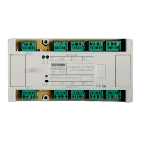
In any case, use a small screwdriver to press the PGM button, through the hole when the system requires
it, in order to codify the lines of this decoder. See diagram on the previous page.
It is also possible to program the decoders from the telephones, if audiodecoder is V1.1 or
higher, and always in MDS Digital installations, it not being necessary to press the PGM but-
ton at the decoder, just the lock button on the telephone. See the MDS Programming Manual
for further details.
The LED indicator in the decoders gives us important information about their status:
OFF: decoder still has not been programmed.
ON: decoder is in programming mode.
BLINKING: decoder has been codified and is working.
* blinks twice every 3 seconds: indicates that the Central Unit in which the
decoder is connected to is in day mode.
* blinks once every 3 seconds: indicates that the Central Unit in which the
decoder is connected to is in night mode.
The DAY and NIGHT modes are a property of the central unit.
The audiodecoders have a telephone jack socket which gives the installer the possibility to plug-in a
standard FERMAX handset to speak from the decoder to an outdoor panel or to any telephone connected
to this decoder.
This telephone jack, which is connected directly to audio lines of the BUS installation, is a great help to the
installers when they are programming the system. An installer can stay at the outdoor panel for program-
ming, while another goes by the decoders pressing the PGM button (or the lock telephone button if possi-
ble).
Both can talk to each other through the handset connected to the telephone jack socket on the decoder
that they are programming at any time).
The technical data for each kind of decoder is:
Audiodecoder calling: 400 mA
Audiodecoder in stand-by: 40 mA
Sensor decoder: 40 mA
Relay decoder: 160 mA (maximum)
Operating voltage: 12 Vdc (minimum 10 Vcc)
 Loading...