Pag. 17
Technical Book
MDS
MDS
SB
6
2
SA
CT
+
-
V
M
P1
M
SA
SB
6
2
-
+
CT
V
M
D1
D2
2
6
CT
V
+
-
G
B
G
A
32
SW1
1
ON
A
B
PANEL 1
SWITCHERS
PIN_PADSTACKPIN_PADSTACKPIN_PADSTACKPIN_PADSTACKPIN_PADSTACKPIN_PADSTACK
PANEL 0
INPUT
DECODERS
+-
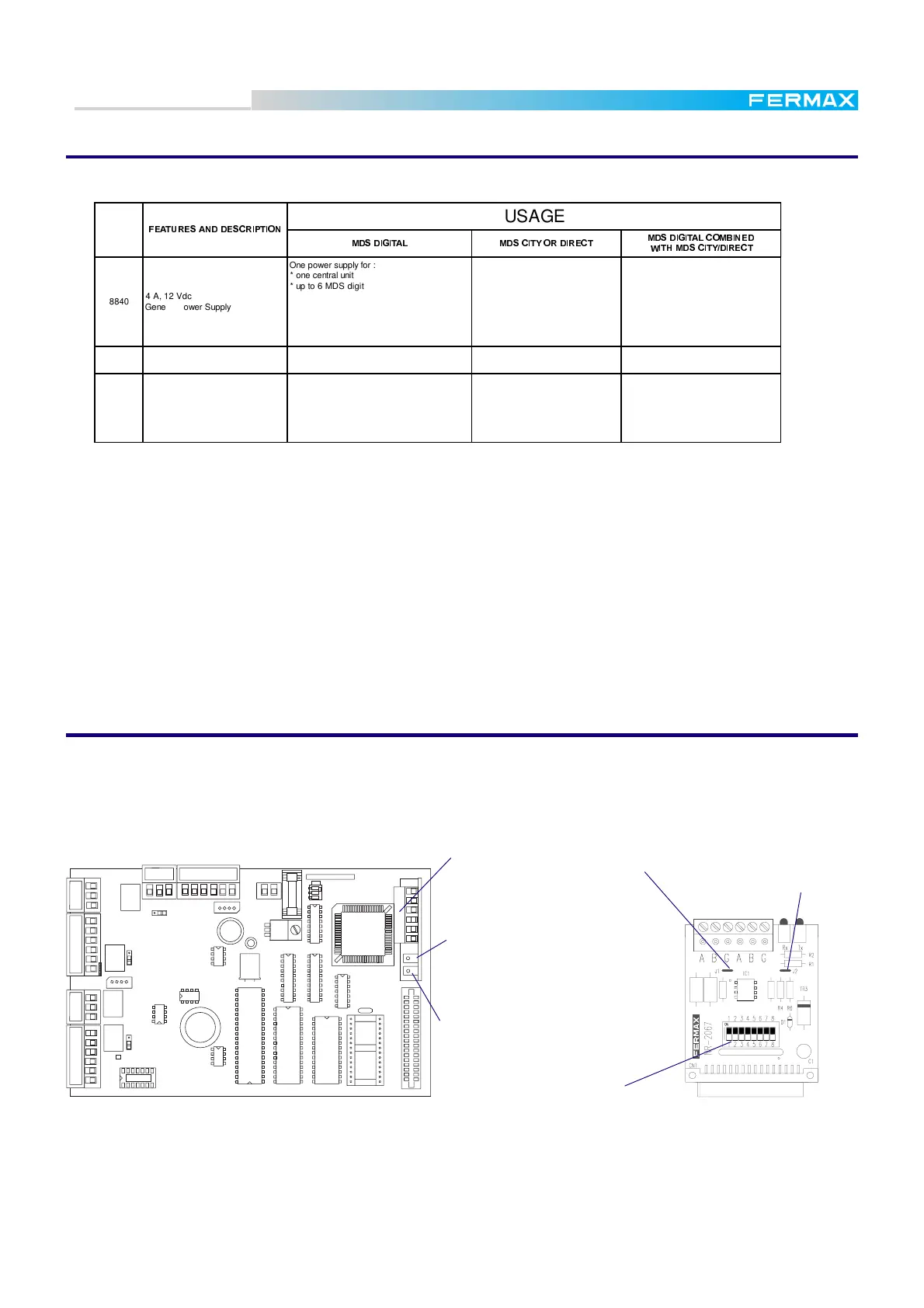
MDS - BASE MODULE
EXTENSION INTERFACE
FXL Network card ref. 2428
The way to connect several MDS-DIGITAL Central Units is by means of the FLX network (FERMAX LINK).
It is possible to link up to 64 Central Units. When the Central Units are linked, the maximum number of
Outdoor Panels per Central Unit will be 31, since the FXL CARD uses the PANEL 0 position. Each card
includes a set of microswitches to configure the following data (see switches table on next page)
Notes:
* If the system has only two linked Central Unit cut both J1 and J2 only in the module installed into the first
Central Unit. This is to share the "pull up" and "pull down" resistances.
* If the system has more than two Central Units, cut both J1 and J2 in all the modules, except in one of them
installed in the middle of the system. This is to avoid excessive "pull up" and "pull down" resistances.
FXL card inserted
in its connector
Configuration switches
Jumper "J2". See note
Jumper "J1" See note
"Rx" LED. It blinks while
this module is receiving data from
the FXL.
"Tx" LED. It blinks
while module is sending data to
the FXL.
MDS Power Supplies
The following power supplies are suitable for MDS systems:
Note
* The number of decoder that can be supplied by the same power source depends on the wire section used
and the distance between them, as long distances and thin wires increase the resistance.
See page 9 for the dependence between the distance and the maximum number of decoders that can be
supplied with the same power supply.
For the same reason, the number of monitors that can be supplied depends on the section and wire length.
60 monitors are estimated using the ref. 5919 FERMAX wire, and up to 300m. from the Power Supply up
to the last monitor.
* Using one emergency battery (Ref. 2070 or 2337)connected to each ref. 8840 Power Supply, the audio
system (not video) can work in the event of power failure. Autonomy is estimated at 40 minutes, but
depends on the use. Ref. 8837 Power Supply already includes an internal built-in battery.
REF.
)($785(6$1''(6&5 ,37,21
USAGE
0'6 ',*,7$/ 0'6&,7< 25',5(&7
0'6 ',*,7$/&20%,1('
:,7+0'6&,7< ',5(&7
8840
4 A, 12 Vdc
General Power Supply
One power supply for :
* one central unit
* up to 6 MDS digital panels
* up to 120 decoders. See note below.
To recuperate the droping voltage along the
bus decoder (see page 9).
One power supply for :
* one central unit
* up to 6 MDS digital panles
* up to 120 decoders. See note below.
To recuperate the droping voltage along
the bus decoder (see page 9).
8830
4 A, 18 Vdc
Video Power Supply
One power supply every 60 monitors . See
note below.
One power supply every 60 monitors.
See note below.
One power supply every 60 monitors.
See note below.
8837
0,75 A, 12 Vdc
(with build-in battery)
Auxiliary Power Supply
To recuperate the droping voltage along the
bus decoder (see page 9)
One power supply for every MDS
DIRECT/CITY panel and up to 40
decoders. See note below.
One power supply for:
* one MDS DIRECT/CITY panel
* up to 40 decoders. See note below.
To recuperate the droping voltage along
the bus decoder (see page 9).
 Loading...