Pag. 16
Technical Book
MDS
MDS
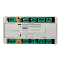
The only difference between Ref.2420 and Ref.2421 is that the Ref.2421 includes an MDS-SWITCHER
MODULE, represented in the figure below, which is connected to the NR-2055 Module by means of a flat
cable, extending the capacity of 2 audio/panels (Ref.2420) up to a maximum of 10.
This MDS-SWITCHER MODULE allocates up to 8 Switcher Cards, which are inserted in the slots (see
figure).
VERY IMPORTANT NOTES:
* The two panels connected to the NR-2055 card do not need Switcher Cards, since the NR-2055 already
includes them, but use one switcher card for each outdoor panel you have to connect into the MDS-
SWITCHER MODULE (Panel connectors 2 to 9) inserting it into the corresponding slot beside the connector.
* Configure the corresponding panel number matching with the panel number connector in which it has
been inserted. Se pages 22 to 25.
* Access control panels can be connected to any panel connector. They can be connected even directly to
any other panel already installed. Do not need switcher card, but it is neccessary to configure its dipswitches
with a panel number not used by any other panel in the same central unit.
* Use Panel 1 connector for the first outdoor panel and reserve Panel 0 connector for the second outdoor
panel (if there is one), Guard Unit or FXL (if the Central Unit is linked to others).
* In FXL installations, Panel 0 is always reserved for the FXL audio communication.
* J1 to ON position directly enables audio between Panel 1 and the decoder bus. Therefore, by inserting a
telephone handset in the test connector of any decoder it is possible to have check audio with the outdoor
panel. This feature is useful when checking or programming the system. The same happens for J0 (with
Panel 0). Whenever these jumpers are set to ON, the corresponding LED (P0 or P1) are on. The LEDs are
also activated when the Central Unit enables the outdoor panel. Do not forget to put J0 or J1 back to its
normal (OFF) position, after checking.
Equivalent LEDs are placed in the Switcher cards to indicate audio activated. The difference is that these
cards do not have activation jumper
* SW1-2 PC TEST MODE has to be put to ON position only when the Decoder PC Intercace Ref. 2466 is
being used, to program decoders or to check the system.
Note that system is then blocked and display shows the message "In Maintenance".
* In case the system is working as Digital Controller, SW1-3 is used to enable the PIN CODE feature. Permission
to open the door is then controlled by means of the PC programming. See PC Programming Manual for
further details.
1. Flat cable from the Central Unit.
2. Panel connector.
3. Power supply connector.
4. Video connector.
5. Switcher extension socket.
3 4 5
7
6
1
2
8
SWITCHERS BASE MODULE
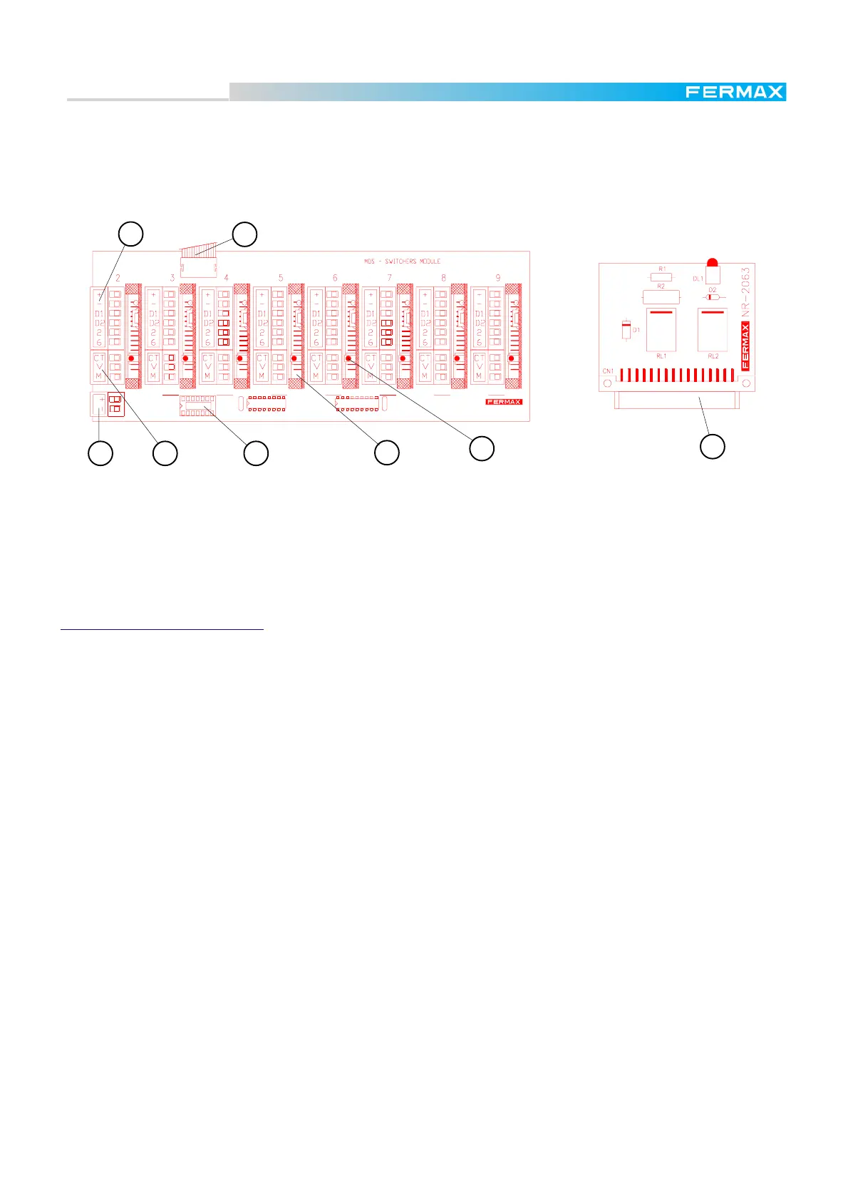
SWITCHER CARD REF.2422
6. Switcher Card (inserted into their slot).
7. Status led indicator. It is on while the
corresponding audio panel is in use
8. Switcher Card socket.
 Loading...