Pag. 13
Technical Book
MDS
MDS
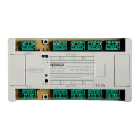
Video Distributor 4 Ref. 2418 & Video Distributor 8 Ref. 2419
These devices are used in video installations only. Video distributors are normally placed beside the stan-
dard decoder and they are responsible for distributing the video signal for each monitor. Video distributors
are activated by the decoder they are attached to, whenever a call is generated in that decoder. The de-
coder thus sends a trigger signal through terminal "V", which is used to activate the distributor. As with the
standard decoders, the video distributors are manufactured in two versions or models: REF.2418 for 4
monitor (normally attached to Audiodecoder 4 Ref.2424) & Ref.2419 for 8 monitors (when Audiodecoder 8
is used REF.2425).
The Video distributors do not need to be programmed.
M
MV
-+
M
+
V
-
V
M
-+
V
+-
V
+-
M
D
IS
T
R
IB
U
ID
O
R
D
E
V
ID
E
O
8
V
ID
E
O
D
IS
T
R
IB
U
T
O
R
8
DISTRIBUIDOR/DISTRIBUTOR Nº:
BUS
PGM
BUS
- V
M
A
D
E
IN
S
P
A
I
N
REF. 2419
5
3
MONITOR
1
6
2
78
4
PG
BU
-
BUS
V
+-
Decoder PC Interface Module Ref.2466
This module is used for programming the decoders, either before installation, using the PC Programming
Connector included in each of them, or after installation (using any PC Programming Connector in any
decoder connected to the MDS BUS or even from the PC Programming Connector in the Central Unit).
It can also be used for testing procedures, after installation. See included DECOWIN instructions for
further details.
Rx
Tx
On
DISTRIBUTOR 4/L
VIDEO
+
VM
+
BUS
V
-+
M
BUS
V
-
-
VIDEO
REF. 2418
-+
V
1
+
M
-
23
-
V M
+
4
V M
-
V M
ISODECODER 4
REF. 2426
TELEPHONES
D2
BUS
+ -
D1
2 6
XX
PGM
-
V
2
4
31 2 4 6 P
1
3
X
+
1234
D1
BUS
6
D2
2
-+
P
+
X4 63
+
1 2PX6
+
6 PX
4321
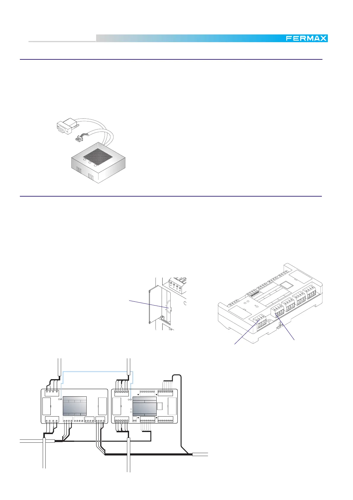
Do not forget to set the SW1-2 configuration microswitch in
the Central Unit ( PROGRAMMING DECODER mode) to ON
position, during the programming process, and return it to
OFF positon afterward. See page 14.
75 ohms load resistor
Cut junmper in all the decoder except in the last
one in the riser. See scematic diagrams.
Do not forget the "V" wire between audio decoder
and video distributor.
See figure alongside.
Monitor connector
8 units.
Video BUS
connector
 Loading...