7
Description of the component
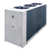
1. Fans. Axial type, they are contained in a sheet nozzle and are equipped with a safety grille, scythe-shaped blades increase the
efficiency and reduce the noise level. The fans are directly coupled to the single-phase motor by means of an external rotor. Thermal
protection against operating faults is installed inside the winding. The fans rotational speed can be modulated continuosly by an
analogue device or an inverter (option) to control the condensation pressure (in cooling) and the evaporation pressure (in heating)
in order to extend the operating limits of the unit and to reduce noise emissions. Optionally are available Electronically Commutated
(EC) fans, which ensure maximum energy efficiency at reduced speed of rotation.
2. Electric control and monitoring panel. It contains all the power, control and security components necessary to guarantee the
unit to work properly. The unit is managed by a microprocessor controller to which all the electrical loads and the control devices are
connected. The user interface, placed on the frontal panel, allows to view and to modify, if necessary, all the parameters of the unit.
This is housed in a metal casing in which the various electrical components are positioned on one metal plate.
2a. The power section includes:
• Main door-locking circuit-breaker.
• Fuse-holder that can be isolated with protection fuse triad for each compressor, or thermal magnetic circuit breakers (option).
• Fuse-holder that can be isolated with protection fuse for compressor oil heaters and antifreeze (if installed), or thermal magnetic
circuit breakers (option).
• Control contactor for each compressor or soft starters (option).
• Protection fuse for the fans, or thermal magnetic circuit breakers (option).
• Thermal magnetic contactor switch to protect the pump (if the Hydronic Kit is installed).
• Phase presence and sequence monitoring device on power supply, or voltage monitor and sequence meter (accessory).
2b. The auxiliary section includes:
• Fuses on the auxiliary transformer, or thermal magnetic circuit breakers (option).
• Electromagnetic noise filter
• Adjusting fan speed board (option)
• Insulating and safety transformer to power the auxiliary circuit.
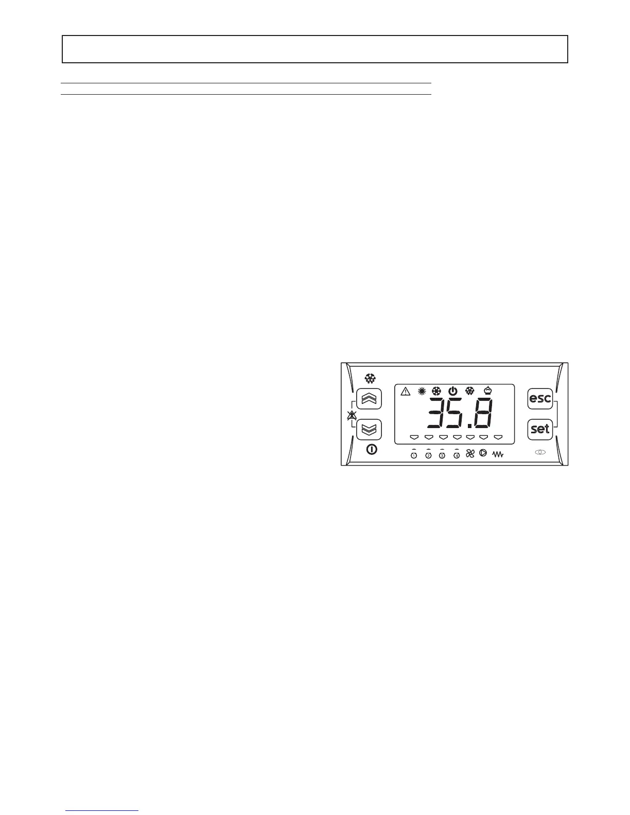
2c. The microprocessor monitoring section includes:
• User interfacing terminal with display.
• On-off key.
• Operating mode selector key.
• Compressor on-off display LED.
• Operational mode LED
• Antifreeze heaters activated indicator LED.
• Fans on-off dislay LED
• Pumps on-off display LED
• Check-control with fault code display
• Defrosting, alarm, economy, stand-by LED.
Control system main functions:
temperature control of the water produced by the unit, compressor and pump operating hour counter, timing and cycling of start-ups,
input parameters by keyboard, alarms management, smart defrosting control and operating mode change (only IP unit), dynamic set-
point (climatic control), scheduling and integrative heaters control.
If you installed the hydronic kit these functions are enabled: antifreeze with pump, start-up cycle after prolonged inactivity (anti-
sticking), if the hydronic kit installed has 2 pumps there is a cycling between each pump to ensure an equivalent lifetime, with inverter
modulating hydronic kit the water flow of the plant can be adjusted.
Digital input functions: low pressure, high pressure, high temperature on compressor supply, phase presence and sequence mo-
nitoring device on power supply, differential water pressure control, compressors thermal protection, fans thermal protection, pumps
thermal protection (only if installed MP accessory), ON/OFF and remote operating mode change, demand limit and Economy function,
recovery enabling (only for the VR Version), recovery Pump Thermal Protective (only for the VR Version), recovery differential water
pressure control (only for the VR Version).
Digital output functions: compressor start-up, pump start-up (only with MP accessory), plate heat exchanger electrical heater,
remote general alarm, 4-way valve (only IP unit), integrative heaters and clean contact on compressors start-up, recovery valve ma-
nagement (only for the VR Version), recovery pump management (only for the VR Version).
Analogic input functions: in and out water temperature, coil temperature probe, external air temperature probe (if present), in and
out recovery water temperature (only for the VR Version).
Analogic output functions: continuous adjustment of axial fans rotating speed (option for AB and standard for AS and AX acoustic
setting up), continuous adjustment of pump rotating speed (only if hydronic kit with modulating pump is installed).
GENERAL FEATURES
°C
MODE
 Loading...