45
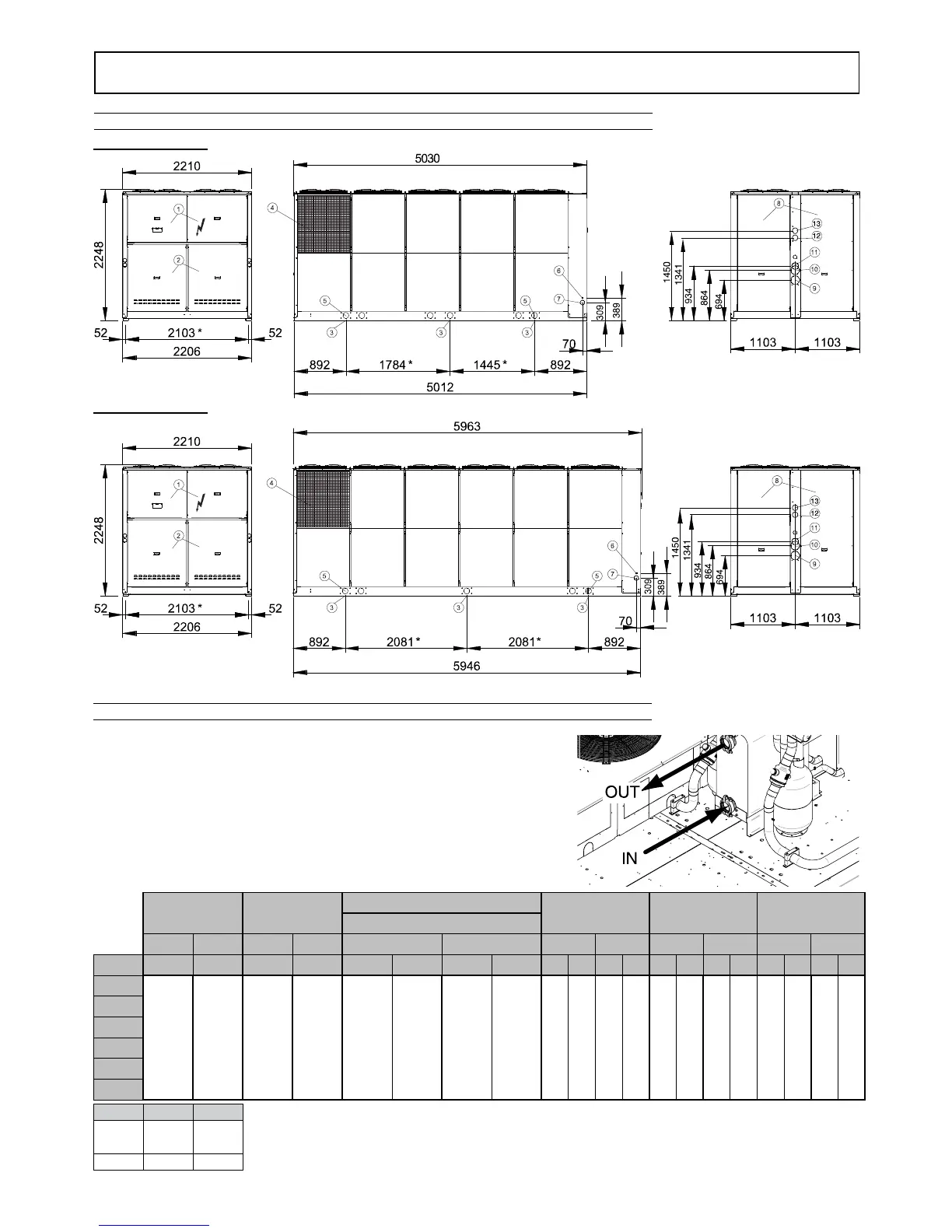
DIMENSIONAL DATA
Overall dimensions
Description of the components
1 - Access panel to electric panel’s power section
2 - Access panel to compressor compartment
3 - Vibration damper fixing holes (6 pcs)
4 - Coil protection grilles (accessory)
5 - ø 100 mm lifting holes
6 - ø 22 mm input hole for accessory cables
7- ø 79 mm hole for electric power supply input
8 - Access panel to pump compartment
Mod. 350.5 ÷ 490.6
Mod. 560.6 ÷ 630.6
VICTAULIC CONNECTION KIT
9 - Water inlet AM PS SS
10 - Water outlet AM PS
11 - Water outlet SS
12 - Water inlet VD
13 - Water outlet VD
* : Center distance of vibration damper
holes
Ø DN Type
2" DN50 Victaulic
3" DN80 Victaulic
4" DN100 Victaulic
WITHOUT KIT
OR MP
VICTAULIC
CONNECTION
KIT
COMPLETE PIPE KIT
MP AM
MP PS
MP SS VD
WATER STORAGE TANK PIPE KIT
IN OUT IN OUT IN OUT IN OUT IN OUT IN OUT
Mod. Ø Ø Ø Ø Ø Ref. Ø Ref. Ø Ref. Ø Ref. Ø Ref. Ø Ref. Ø Ref. Ø Ref.
350.5
3" 3" 4" 4" 4" 9 4" 11 4" 9 4" 10 4" 9 4" 11 2" 12 2" 13
390.6
440.6
490.6
560.6
630.6

 Loading...