54
ELECTRICAL CONNECTIONS
Compressor specification
General rules
The appliance must be wired in compliance with the laws in force in the country in which it is installed. The units are supplied fully
wired in the factory and pre-engineered for connection to the electricity main. The electric panel is made in compliance with the tech-
nical standards in force in the European Union.
Structure of the electric panel
All the electrical components are contained in a closed casing protected against the atmospheric agents and inspectionable by ope-
ning the front door after removing the front panel. The door for accessing the power section is locked by the mechanism.
Access for the supply cables and earth cable (PE) is permitted through the opening on the botton of the electric panel.
Composition of the system
The system comprises an electromechanical part consisting of the power circuit, with disconnecting device, contactors, fuses or
thermal cutouts, transformer, and another part comprising the Microprocessor control system.
NOTES: Refer to the wiring diagram supplied with the unit for the layout of the electric panel.
Electrical connections
All electrical connections must be carried out by qualified personnel in the absence of electric power. The table below gives the elec-
trical specifications of the different constructional configurations of the units.
UNIT
350.5 390.6 440.6 490.6 560.6 630.6 UM
Power supply 400 - 3 - 50 V-ph-Hz
FLA [A]
CP1A
59.3
44.6 44.6 59.3 59.3 73.8
A
CP1B 59.3 44.6 44.6 59.3 59.3 73.8
CP1C - 44.6 44.6 59.3 59.3 73.8
CP2A 44.6 44.6 59.3 59.3 73.8 73.8
CP2B 44.6 44.6 59.3 59.3 73.8 73.8
CP2C
44.6
44.6 59.3 59.3 73.8 73.8
LRA [A]
CP1A
310
272 272 310 310 394
A
CP1B 310 272 272 310 310 394
CP1C - 272 272 310 310 394
CP2A 272 272 310 310 394 394
CP2B 272 272 310 310 394 394
CP2C
272
272 310 310 394 394
FLI [kW]
CP1A
36.1
27.6 27.6 36.1 36.1 46.7
kW
CP1B 36.1 27.6 27.6 36.1 36.1 46.7
CP1C - 27.6 27.6 36.1 36.1 46.7
CP2A 27.6 27.6 36.1 36.1 46.7 46.7
CP2B 27.6 27.6 36.1 36.1 46.7 46.7
CP2C
27.6 27.6 36.1 36.1 46.7 46.7
Winding
resistance
ohm [Ω]
CP1A
0.349 0.514 0.514 0.349 0.349 0.300
Ω
CP1B 0.349 0.514 0.514 0.349 0.349 0.300
CP1C - 0.514 0.514 0.349 0.349 0.300
CP2A 0.514 0.514 0.349 0.349 0.300 0.300
CP2B 0.514 0.514 0.349 0.349 0.300 0.300
CP2C
0.514 0.514 0.349 0.349 0.300 0.300
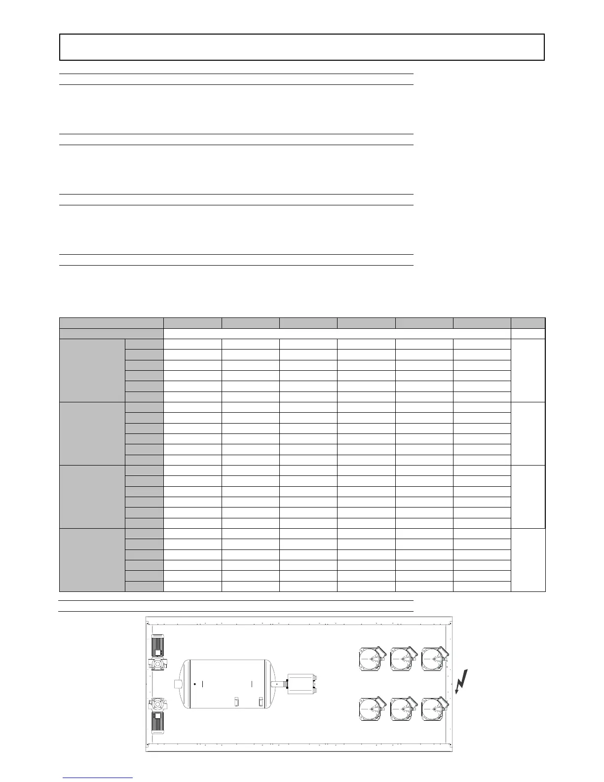
CP2C
HEAT
EXCHANGER
PUMP 2
TANK
PUMP 1
CP2B CP2A
CP1C CP1B CP1A
Unit layout

 Loading...