2 Description of the safety function STO
Festo – GDCP-CMMS-AS-G2-S1-EN – 1306NH – English 17
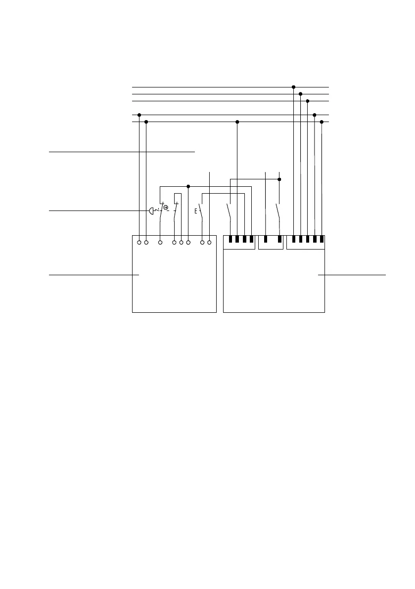
2.3 Switching example S TO – “Safe Torque Off”
12
3
T1
Pilz PNOZ s3
A1
S11
S12
S21
S22
S34
Y32
S1
22
21
A2
11
12
S2
T2
Festo CMMS-AS-...-G2
+24V
0V
-X9
T1
219
DIN4
DIN5
-X1
2 3
REL
0V
C2NC2
NC1
-X3
13
14
23
24
T1
PE
Input T3
acknowledgment
T1
13
14
N
L1
24 V DC
0VDC
Only relevant connections drawn
Output T3
controller enable
Output T3
hardware enable
56
4
1 Motor controller with safety function
(T2, only relevant connections represented)
2 Safety switching device (T1)
3 Emergency stop switches
4 Inputs and outputs of the higher-order
controller (T3, 24 V)
Fig. 2.3 Circuit diagram, safety function STO
2.3.1 Ex planations of the switching example
The switching example shows a c ombination of the CMMS-AS-...-G2 with a PNOZ s3 safety switching
device from Pilz. A circuit is shown with an emergency stop switch that carries out the safety function
“Safe Torque Off (STO)”. The emergency stop switch (S1) can be replaced by another safety command
device,e.g.safetydoorswitch.
You c an find tec hnical data, such as max. current, etc., in the data sheet of the safety switching devices.
Due to the drawn circuitry, a two-channel operatio n with cross-circuiting recognition is possible. This
permits recognition of:
– earth faults in the star t and input c ircuit.
– short circuits in the input circuit / start circuit.
– cross circuits in the input circuit.
The removal of output stage enable via DIN4 [X1.21] as well as switching off of the driver supply via Rel
[X3.2] results in the motor coasting to a stop.
 Loading...


