3 Assembly and installation
Festo – GDCP-CMMS-AS-G2-S1-EN – 1306NH – English 29
3.2.2 Ports [X1] and [X3]
The motor controller CMMS-A S -...-G2 has digital inputs for the integrated safety function at the plug
connectors [X1] and [X3].
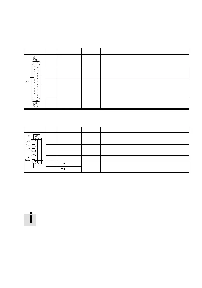
Plug [X1]
Pin Allocation Value Description
1
6
9
21
18
6 GND24 0V Reference potential for digital inputs and outputs.
9 DI N5 0V/24V Controller enable (high active).
18 24 V +24 V DC Auxiliary power supply ( 24 V DC logic supply of the
motor c ontroller provided).
21 DIN4 0V/24V Output stage enable (high active).
Tab. 3.1 Pin allocation [X1], only for connections relevant for the safety function (representation of
the plug on the device)
Plug [X3]
Pin Designation Value Des cription
1
6
1 24 V +24 V DC Auxiliary power supply (24 V DC logic supply of the
motor c ontroller provided).
2 Rel 0V/24V Driver supply relay control.
3 0V 0V Reference potential for digital inputs and output s.
4 – – –
5 1(NC1)– Acknowledgment contact for the status “Safe Torque
Off ” (STO)
6
2(NC2)
Tab. 3.2 Pin allocation [X3] (representation with plug on the device in the scope of delivery)
To ensure the function STO “Safe Torque Off ”, the control ports DIN4 [X1.21] and Rel [X3.2] must be
connected in two channels through parallel wiring Section 2.3, Fig. 2.3.
This interface c an be part of an emergency stop circuit or a protective door arrangement, for example.
Carry out the connection corresponding to S ec tion A.1.3, Tab. A.9.
You will find switching examples in Section 2.3 and 2.4.
 Loading...


