2 Description of the safety function STO
26 Festo – GDCP-CMMS-AS-G2-S1-EN – 1306NH – English
2.4.5 Parameterisation example
Setting the switch-off delay
The switch-off delay of the holding brake must be set in the FCT on the “Motor” page , “Brake c ontrol”
tab. The set time is necessary, as the brake does not close immediately due to the mechanics. If this set
time = 0 or <= 10 ms, vertically hanging loads can briefly slip through.
Determination of the brake time
The brake time can be determined with the FCT Trace Function. The brake time can vary greately due to
different travel speeds and delays. Determine the values for the maximum brake time with maximum
travel speed.
To do this, select the actual speed value in the FCT on the “Configure measurement data”.
Then perform a measurement (“Start trace”).
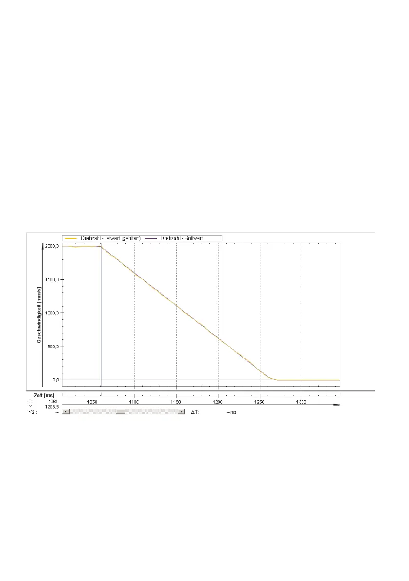
Duringthemeasurement,removethecontrollerenableandsodeterminethebraketimefromthe
measurement curve on the “Measurement data” page. A typical measurement cur ve can look as fol-
lows.
Fig. 2.7 Typical measurement c urve for determination of brake time
Calculation example:
1. Graphically read brake time (t2): 210 ms.
2. Parameterised switch-off delay for the brake : 150 ms (from FCT)
Delay time until output stage from (t4): 5 ms (fixed)
3. Sum: 210 ms + 150 ms + 5 ms = 365 ms
Plan a safety reserve for dispersion of the brake times, e.g. 10 %.
4. Set th e delay time of the PNOZ (t5) to 400 ms.
 Loading...


