2 Description of the safety function STO
Festo – GDCP-CMMS-AS-G2-S1-EN – 1306NH – English 21
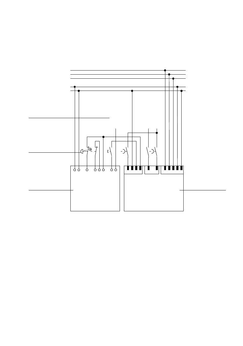
2.4 Switching example SS1 – “Safe Stop 1”
In the function “Safe Stop 1” (SS1), the drive is run down in a c ontrolled way and, after that, the power
supply to the final output stage is switched off. As a result, the drive cannot generate torque or any
force at rest and so cannot make any dangerous movements.
12
3
A1
S11
S12
S21
S22
S34
Y32
S1
22
21
A2
11
12
S2
+24V
0V
-X9
T1
219
DIN4
DIN5
-X1
REL
0V
NC2
NC1
37
38
47
48
T1
13
14
T1
T1
Pilz PNOZ s5
T2
Festo CMMS-AS-...-G2
PE
Input T3
acknowledgment
T1
N
24 V DC
0VDC
Only relevant connections drawn
Output T3
controller enable
Output T3
hardware enable
13
14
L1
2 3
-X3
56
4
1 Motor controller with safety function
(T2, only relevant connections represented)
2 Safety switching device (T1)
3 Emergency stop switches
4 Inputs and outputs of the higher-order
controller (T3, 24 V)
Fig. 2.5 Circuit diagram for the safety function SS1
2.4.1 Ex planations of the switching example
The switching example shows a c ombination of the CMMS-AS-...-G2 with a PNOZ s5 safety switching
device from Pilz. As switching device, a safety stop is drawn in combination with an emergency stop
switch. There remains the option to use a protective door switch with bolt that holds the protective
door close until the drive is at rest or the “driver supply feedback” signal displays the safe status and
the plausibility check is successful.
You c an find tec hnical data, such as max. current, etc., in the data sheet of the safety switching devices.
 Loading...


