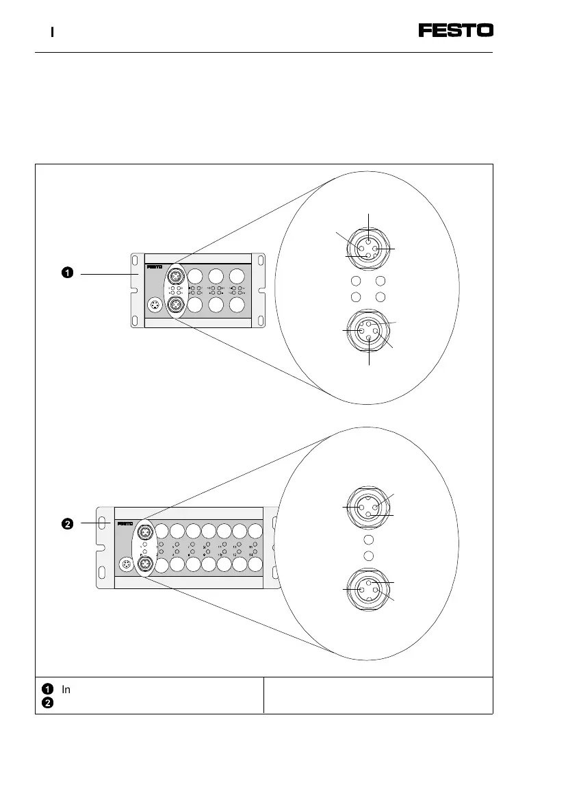
Pin assignment
The diagram below shows the pin assignment of the
sensor connections as an example.
1
2
Input module type CP-E16...-M12x2
Input module type CP-E16...-M8
E = Input
Fig. 1/5: Pin assignment of input module
Ex+3
Ex
Ex+2
Pin 3: 0V
Pin 4: Ex
Pin 1: 24V
Pin 4: Ex+2
Pin 3: 0V
Pin 2: Ex+3
Ex+1
Pin 1: 24V
Pin 2: Ex
Pin 3: 0V
Ex+1
Ex
2
1
1. Input module type CP-E16...-M...
1-10 CP-E16...-M... 9611A