2. Commissioning
2-41
Festo P.BE-FB14-EN en 1411d English
2.4 Object directories
2.4.1 Communication profile
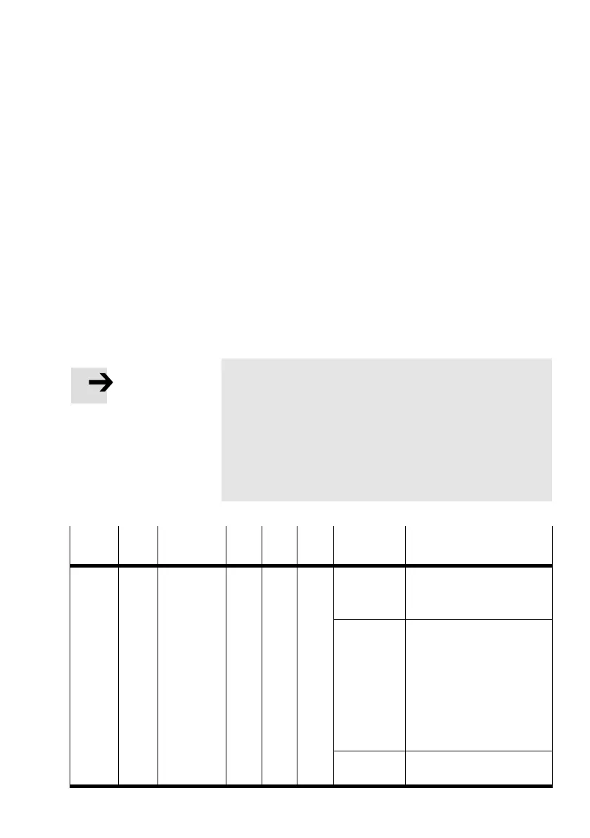
The following tables show the objects of the communication
part (values and examples: module ID = 1).
In the following: U = unsigned
ro = read only
rw = read/write
Map. = mapping possible
Attr. = attribute
Note
For mapping, the rules in accordance with CiA 301 apply:
Mapping entries are only possible if the number of para
meters has previously been set to zero.
(Example: index 1O00, subindex 3 … 8:
Set subindex 0 to “0”).
After entering the mapping values, set the number of para
meters to the corresponding value again.
Index
(hex)
Sub
index
Designa
tion
Type Attr. Map. Values
(hex)
Explanation
1000 0 Device type U32 ro – 00 0F 91 01 From software version V1.10:
OF = maximum expansion of
the CPX terminal
00 0x 91 01 Prior to software version
V1.10:
91 01 = device profile
x = dependent on expansion
of the CPX terminal:
Bit 16: digital inputs
Bit 17: digital outputs
Bit 18: analogue inputs
Bit 19: analogue outputs
Example:
00 03 91 01
CPX terminal with digital
inputs and outputs
 Loading...


