8
range. Cracked or distorted cutters must not be
used.
We recommend that milling cutters with diam-
eters over 30 mm should not be used with this
machine.
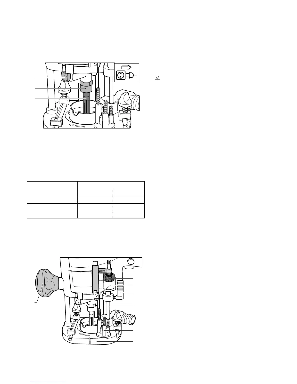
Inserting the tool
- Insert the router (6.3) into the open clamping col-
let as far as possible, but at least up to the mark
on the router shank.
- Turn the spindle until the spindle stop (6.1) catches
when pressed and the spindle is locked in place.
- Tighten the collet nut (6.2) with a 19 mm open-end
spanner.
Removing the tool
- Turn the spindle until the spindle stop (6.1) catches
when pressed and the spindle is locked in place.
- Loosen the collet nut (6.2) using a 19 mm open-
ended spanner until a resistance is felt. Overcome
this resistance by turning the open-ended span-
ner even further.
- Remove the cutter.
Clamping collet changing
- Fully unscrew the collet nut (6.2) and remove from
spindle together with the clamping collet.
- Only insert a new clamping collet in the spindle
when the nut is attached and engaged, then
tighten the nut slightly. Do not tighten the collet
nut until a milling cutter has been fi tted!
Adjusting the milling depth
The milling depth is adjusted in three stages:
a) Setting the zero point
- Open the clamping lever (7.4) so that the stop
cylinder (7.5) can be moved freely.
- Place the router with router table (7.7) onto a
smooth surface. Open the rotary knob (7.8) and
press the machine down until the milling cutter
rests on the base. Clamp the machine tight in this
position with the rotary knob (7.5).
- Press the stop cylinder against one of the three
sensing stops of the pivoted turret stop (7.6).
- The individual height of each sensing stop can be
adjusted with a screwdriver.
- Push the pointer (7.1) down so that it shows 0 mm
on the scale (7.3).
6.2
6.3
6.1
Cutter shank Clamping collet
Ø Order-No.
Ø 6 mm 6 mm 488 764
Ø 6,35 mm (1/4") 6,35 mm 488 765
Ø 8 mm 8 mm 488 763
7.8
7.3
7.2
7.1
7.4
7.5
7.6
7.7
 Loading...