4
INSTALLATION
#2: Installation
Connecting the Roller Shutter 3 in a manner inconsistent
with this manual may cause risk to health, life or material
damage.
• Connect only in accordance with one of the diagrams,
• Do not connect DC powered motors, the device is dedicated to
operate AC powered electric motors,
• Do not connect the device to loads exceeding recommended
values,
• The device should be installed in a wall switch box compliant with
a relevant national safety standards and with depth no less than
60mm,
• Electrical switches used in installation should be compliant with the
relevant safety standards,
• Length of wires used to connect the control switch should not
exceed 20m,
• Connect roller blind motors with electronic or mechanical limit
switches only.
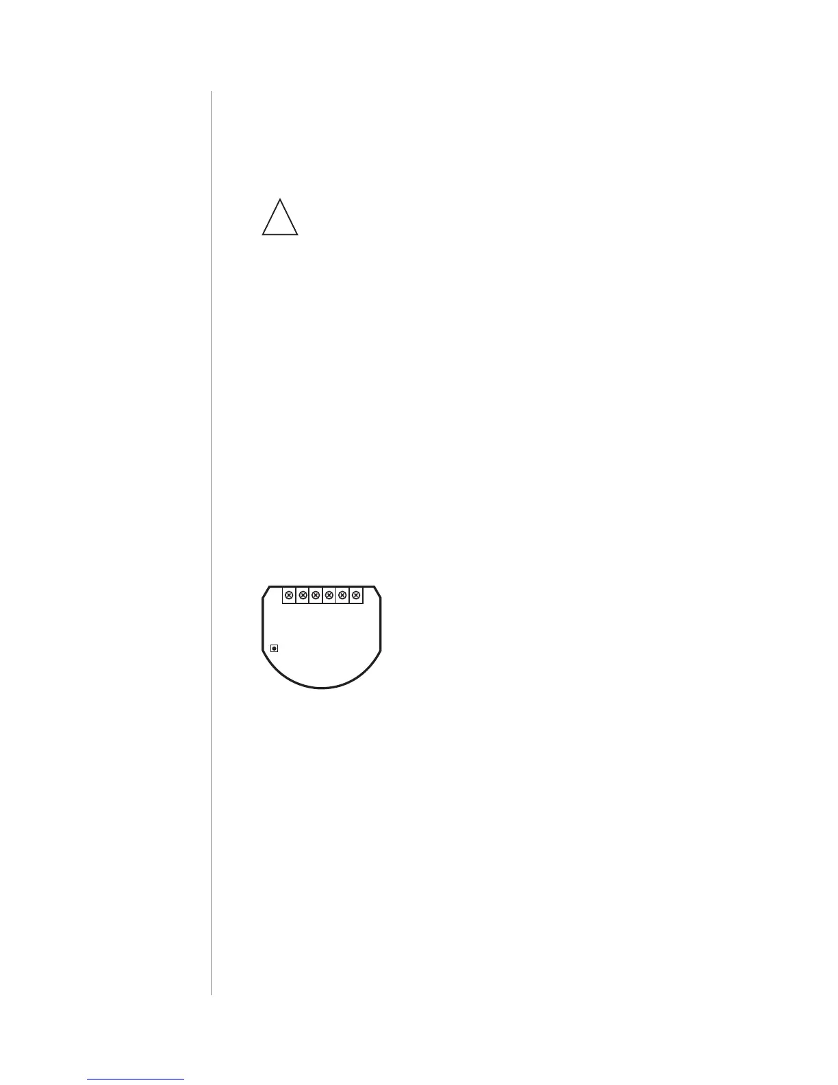
Notes for the diagrams:
S1 - terminal for 1st switch (used to add/remove
the device)
S2 - terminal for 2nd switch
Q2 - 2nd output terminal for shutter motor
Q1 - 1st output terminal for shutter motor
L - terminal for live lead
N - terminal for neutral lead
B - service button (used to add/remove the de-
vice and navigate the menu)
Roller
Shutter 3
L NS1 S2 Q2
B
Q1
Tips for arranging the antenna:
• Locate the antenna as far from metal elements as possible
(connecting wires, bracket rings, etc.) in order to prevent
interferences,
• Metal surfaces in the direct vicinity of the antenna (e.g. ush
mounted metal boxes, metal door frames) may impair signal
reception!
• Do not cut or shorten the antenna - its length is perfectly matched
to the band in which the system operates.
• Make sure no part of the antenna sticks out of the wall switch box.