Reproduction forbidden without Fibocom Wireless Inc. written authorization - All Rights Reserved.
FIBOCOM L850-GL Series Hardware Guide Page 34 of 59
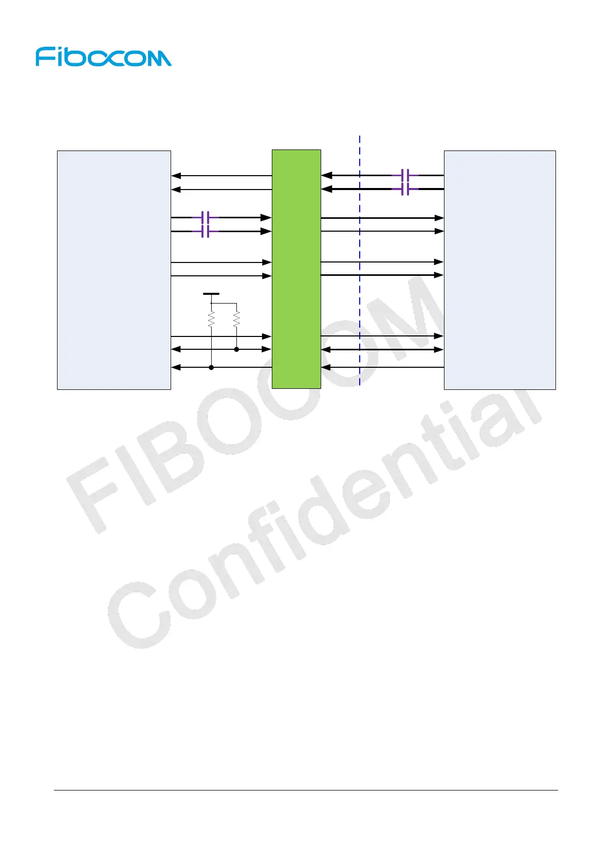
3.4.1.2 PCIe Interface Application
The reference circuit is shown in Figure 3-13:
Module side
AP side
AC Caps
AC Caps
PERST#
CLKREQ#
WAKE#
PERST#(pin50)
CLKREQ#(pin52)
PEWAKE#(pin54)
PERn0
PERP0
PETn0
PETP0
REFCLKN
REFCLKP
PETn0(pin41)
PETP0(pin43)
PERn0(pin47)
PERP0(pin49)
REFCLKN(pin53)
REFCLKP(pin55)
+3.3V/1.8V
100K 10K
M.2 Key-B 75pin
Connector
Figure 3-13 Reference circuit for PCIe interface
L850 module supports PCIe Gen1 interface, one lane. The PCIe interface including three differential pairs:
transmit pair TXP/N, receiving pair RXP/N and clock pair CLKP/N.
PCIe can achieve the maximum transmission rate of 2.5 GT/s, and must strictly follow the rules below in
PCB Layout:
The differential signal pair lines should be parallel and equal in length;
The differential signal pair lines should be short if possible and be controlled within 15 inch (380 mm)
for AP end;
The impedance of differential signal pair lines is recommended to be 100Ω, and can be controlled to
80~120Ω in accordance with PCIe protocol;
Try to avoid the discontinuous reference ground, such as segment and space;
When the differential signal lines go through different layers, the via hole of grounding signal should
be in close to that of signal, and generally, each pair of signals require 1-3 grounding signal via holes
and the lines should never cross the segment of plane;
Try to avoid bended lines and avoid introducing common-mode noise in the system, which will
influence the signal integrity and EMI of difference pair. As shown in Figure 3-14, the bending angle
of all lines should be equal or greater than 135°, the spacing between difference pair lines should be
larger than 20mil, and the line caused by bending should be greater than 1.5 times line width at least.
When a serpentine line is used for length match with another line, the bended length of each segment
 Loading...