EasyManuals Logo

Fibocom L850-GL Series User Manual

Fibocom L850-GL Series
59 pages
To Next Page IconTo Next Page
To Previous Page IconTo Previous Page
Page #55 background imageLoading...
Page #55 background image
Reproduction forbidden without Fibocom Wireless Inc. written authorization - All Rights Reserved.
FIBOCOM L850-GL Series Hardware Guide Page 55 of 59
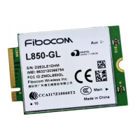
5.3 M.2 Interface Model
The L850 M.2 module adopts 75-pin gold finger as external interface, where 67 pins are signal pins and 8
pins are notch pins as shown in Figure 3-1. For module dimension, please refer to
5.2 Dimension of
Structure. Based on the M.2 interface definition, L850 module adopts Type 3042-S3-B interface (30x42mm,
the component maximum height on t top layer is 1.5mm, PCB thickness is 0.8mm, and KEY ID is B).
Figure 5-3 M.2 interface model
5.4 M.2 Connector
L850 module connects with host by M.2 connector which is built in host. The recommended part number
is APCI0026-P001A manufactured by LOTES Corporation, and the dimensions is shown in Figure 5-4. The
package of connector, please refer to the specification.

Questions and Answers:

Question and Answer IconNeed help?

Do you have a question about the Fibocom L850-GL Series and is the answer not in the manual?

Fibocom L850-GL Series Specifications

General IconGeneral
CategoryGSM/GPRS Modules
ModelL850-GL
Form FactorM.2
Operating Temperature-10°C to +55°C
Storage Temperature-40°C to +85°C
GSM Bands850/900/1800/1900MHz
GNSSGPS, GLONASS, BeiDou, Galileo
InterfaceUSB 2.0, UART, PCM, I2C, GPIO
Operating Voltage3.135V to 4.4V
LTE FDDB1, B2, B3, B4, B5, B7, B8, B12, B13, B17, B18, B19, B20, B25, B26, B28, B29, B30, B66
LTE TDDB38/B39/B40/B41
WCDMAB1, B2, B4, B5, B8
AT Command Set3GPP TS 27.007
CertificationsCE, FCC, GCF, PTCRB