23
ESPAÑOL FRANÇAIS
DEUTSCH
ENGLISH
ITALIANO
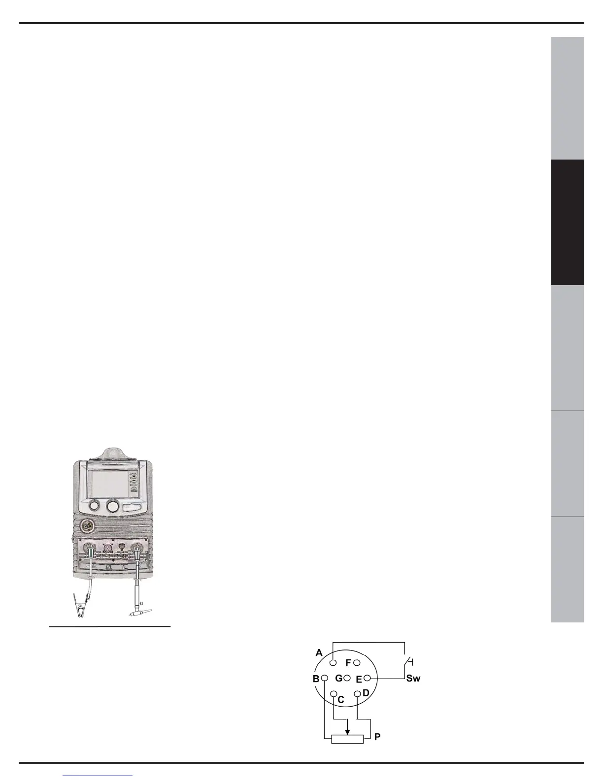
14. CONNECTOR FOR TIG WELDING
1) Connect the earth cable to the appropriate
‘+’ socket on the front of the device (14 of fig.1).
Insert by lining-up the key with the groove
and turn in a clockwise direction until it stops.
Do not fasten too tightly!
2) Connect the torch to the appropriate ‘-‘
socket on the front of the device (12 of fig 1).
3) Insert by lining-up the key with the groove
and turn in a clockwise direction until it stops.
Do not fasten too tightly!
4) Insert the torch pulse signal connector into
the socket
TIG WELDING:
Before connecting the gas make sure the
cylinder contains Inert gas. Never use any
other type of gas.
Connect the pres-
sure regulator to the
cylinder, after whi-
ch, connect the lat-
ter to the gas tube
of the torch.
TIG welding is usual-
ly carried out with a
constant current, with
a negative pole (‘-‘
see fig.6).
The cable of the TIG torch is then inserted
into the negative socket (12of fig.1), whilst
the earth cable of the workpiece is connec-
ted to the positive socket. (14 of fig.1).
At this stage it is possible to adjust the welding
current using the potentiometer (9 of fig. 1) on
the front panel.
The diameter of the electrode and the wel-
ding current settings must be selected accor-
ding to the characteristics of the material
to be welded.
15. POWER CONNECTOR
Before connecting the machine check the
tension, number of phases and the power
supply frequency. The admissible power
supply is indicated on the information plate
on the machine.
Check that the earth of the welder has been
connected correctly. Furthermore, make sure
that the plug provided with the equipment is
compatible with the local grid sockets. Make
sure that the power supply provides sufficient
power for the machine to function (tension
ranges).
The machine is provided with a specific
power cable that does not usually require an
extension lead; in the event an extension
lead is required, use one of the same
capacity or higher than the machine in use,
according to the length of the cable. A 2.5
mm² three-pole cable + earth, of the same
size or larger.
16. REMOTE CONNECTION
Figure 7 shows the connections of the
remote connector (13 of fig 1).
Where:
Sw is the torch
trigger
P is the potentiometer
for controlling the
current.
Fig.6
Fig.7