Document #51003 Rev.E 01/11/02 P/N 51003:E
13
Circuits
1.4 Circuits
SLC Communication Loop
One SLC loop, configurable for NFPA Style 4, 6 or 7, is provided for communication to addressable monitor (initiat-
ing device) and control (output device) modules. Refer to SLC Wiring Manual for additional information.
Output Circuits
The following output circuits are available on the FACP:
• 24 Volt Resettable Power Output 300 mA
• 24 Volt Nonresettable Power Output 300 mA
• 24 Volt Battery Charger (up to 18 AH batteries)
NAC (Notification Appliance Circuits)
Two NACs, configurable for Style Y (Class B) or Style Z (Class A), are provided with various programmable
features.
Relays
Three dry contact relays are provided for System Alarm and System Trouble (Form-C contacts) and Supervisory
(Form-A contacts). Contacts are rated 2.0 amps @ 30 VDC (resistive) and 0.5 amps @ 30 VAC (resistive).
1.5 Components
Main Circuit Board
The main circuit board contains the system's
CPU, power supply, other primary components
and wiring interface connectors. Optional
modules plug-in and are mounted to the main
circuit board. The circuit board is delivered
premounted in the MS-9200 cabinet. Note that
newer versions of the circuit board have jumper
JP1 which can be cut to disable the FACP
battery charger when using an external battery
charger.
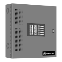
Cabinet
The MS-9200 cabinet is red with an attractive navy blue front overlay. The
backbox provides space for two batteries up to 12 Amp Hour. Refer to Fig-
ure 2-2, “MS-9200 Cabinet Mounting,” on page 24, for information on
dimensions. Ample knockouts are provided for system wiring. Also avail-
able is an optional dress panel, DP-1-B, which mounts to the inside of the
cabinet (required and included on the ULC version). The dress panel must
be installed to meet FM requirements (refer to “Dress Panel” on page 17).
24V UNREG 24V NONRS 24V RST
BELL 2 POWER
BELL 1 POWER
SUPV ALARM TROUBLE PC/PRINTER TERM COMM
GND FAULT
DISABLE
TRANSFORMER 1
TRANSFORMER 2
- +
BATTERY
RS-23 2
PC/PRI NTER
RS-485
TERM. MODE
TROUBLE
+ - + - + -
B+ A+ A- B-
B+ A+ A- B-
NO C NO N C C N O NC C
A B B+ A+ B- A -
1 COMM 2
ACS
SHIELD SLC SL C
OUT+ IN+ OUT- IN-
T
B
4
T
B
2
T
B
1
T
B
3
T
B
7
T
B
5
T
B
6
J16
J6
JP3
JP1
CAUTION
HIGH VOLTAGE
J3
TB8
J19
J17
JP4
SW1
SW3
SW2
CAUTION!
HIGH VOLTAGE
GNDFAULT
JP1
9200bord.cdr
ms9200.cdr