Optional Modules
32
Document #51003 Rev.E 01/11/02 P/N 51003:E
2.8.2 ACM-8RF Relay Control Module
WARNING! Disconnect all sources of power (AC and DC) before
installing or removing any modules or wiring
The ACM-8RF module provides eight Form-C relays with contacts rated
for 5 amps. When installed with an MS-9200 FACP, the ACM-8RF mod-
ules provide relay activation for each of the 56 possible FACP zones plus
special functions. Options exist to allow for alarm only or alarm and trou-
ble activations per zone. Output activation for general alarm, general trou-
ble, general supervisory, NAC fault, AC fail, walktest start and battery
trouble are also available. Refer to the ACM-8RF Manual Appendix for
information on setting module switches for addressing and relay functions.
The ACM-8RF is installed on the standard ACS (EIA-485) communication
bus and wiring is supervised by the FACP. Power for the module must be
power-limited and may be provided by the FACP or a UL listed power sup-
ply such as the FCPS-24F/E. Up to 32 ACM-8RF Relay Control Modules
may be placed onto the EIA-485 communication bus (if no other devices
are installed on the bus). Removable terminal blocks are provided for ease
of wiring installation and servicing. Refer to the ACM-8RF Manual for UL power-limited wiring requirements and
switch SW4 receive/transmit selection options. The ACM-8RF module can be mounted remotely in an ABS-8RF
annunciator surface-mount backbox.
CAUTION: It is vitally important that, following relay programming, all relays be tested for correct activation by
triggering zones and/or special functions at the FACP. It should also be noted:
• ACM-8RF relays will activate
during the Alarm Presignal sequence
• ACM-8RF relays will not activate
during the Alarm Verification Retard and Reset Periods
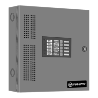
FIGURE 2-13:
ABS-8RF Enclosure
!
24V UNREG 24V NONRS 24V RST
BELL 2 POWER
BELL 1 POWER
SUPV ALAR M TROUB LE
PC/PRINTER TERM COMM
+ - + - + -
B+ A+ A- B- B+ A+ A- B-
NO C NO NC C NO NC C
A B B+ A+ B- A-
1 COMM 2
ACS
SHI ELD
SLC SLC
OUT+ IN+ OUT- IN-
T
B
4
T
B
2
T
B
1
T
B
3
T
B
7
T
B
5
T
B
6
1 2345
6
7812
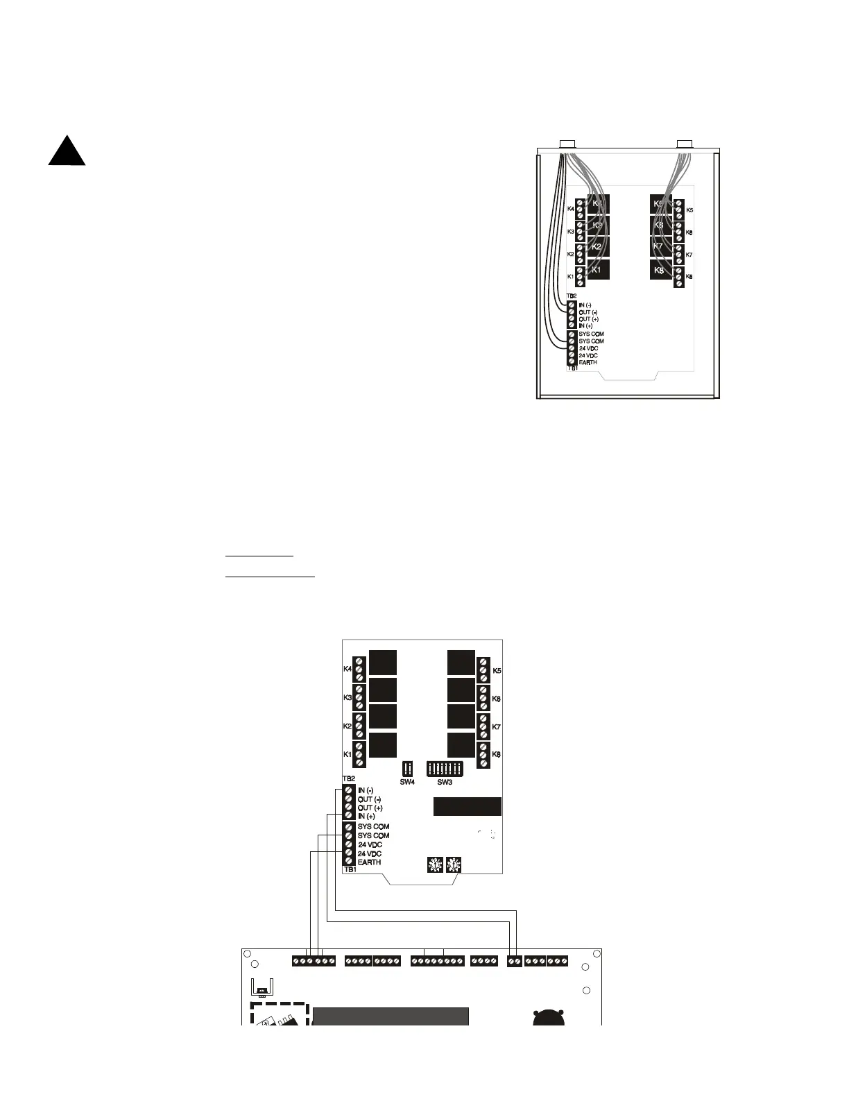
FIGURE 2-14:
ACM-8RF Relay Control Module Installation
ACM-8RF
MS-9200
ACS (EIA-485) TB5-1(+) & 2(-)
Nonresettable 24 VDC
Power Out TB4-3(+) & 4(-)
9200acm8.cdr