Backbox Mounting
24
Document #51003 Rev.E 01/11/02 P/N 51003:E
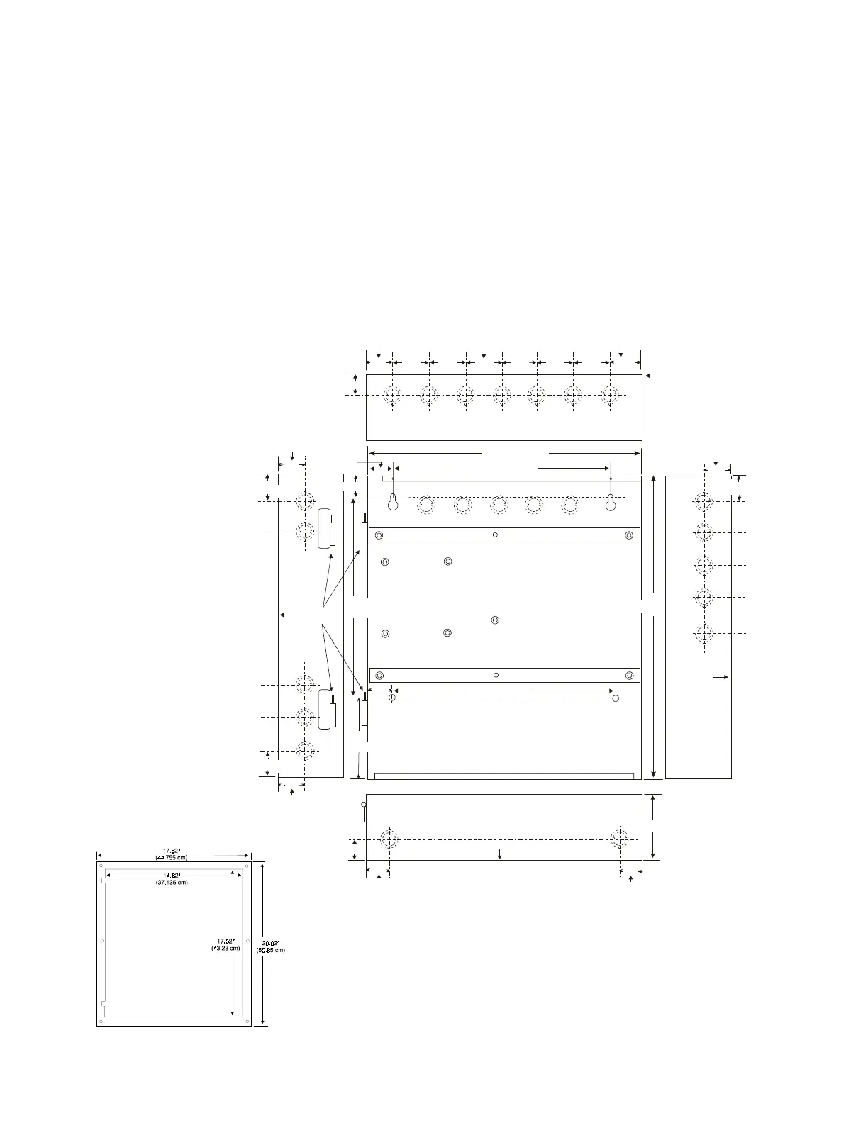
2.1 Backbox Mounting
1.
Remove the main PC board assembly by unscrewing the four screws in the corners of the board. Two stand-
offs support the board in the center. Set the board aside in a safe, clean place. Avoid static discharge which
may damage the board.
2.
Mark and predrill holes for the top two keyhole mounting bolts using the dimensions shown.
3.
Install two upper fasteners in the wall with the screw heads protruding.
4.
Using the upper 'keyholes', mount the backbox over the two screws.
5.
Mark and drill the lower two holes.
6.
Secure backbox by installing the remaining fasteners. Tighten all screws.
7.
When the location is dry and free of construction dust, reinstall the main PC board.
14.5"
16.9“”
11.5"
1.50“
1.235"
1.50“
1.50“
1.62“
1.62“
Hinges
Hinge
Back
of
Box
Back of Box
2.00"
2.00"
2.00" 2.00" 2.00" 2.00"
1.75“
4.445 cm
4.445 cm
1.50“
(3.81 cm)
(3.81 cm)
(3.81 cm)
(3.81 cm)
(3.81 cm)
(4.445 cm)
(4.445 cm)
(11.43 cm)
(3.81 cm)
(36.83 cm)
(29.21 cm)
(5.08 cm)
1.75“
1.50“
4.5“
1.50“
4.6“
1.58“
11.5“
1.75“
1.75“
Back
of
Box
Back
of
Box
(4.115 cm)
(3.14 cm)
(4.115 cm)
(42.926 cm)
(11.68 cm)
(29.21 cm)
(4.115 cm)
(28.10 cm)
11.062"
1.62“
FIGURE 2-2:
MS-9200 Cabinet Mounting
TR-4-R Trim Ring
9200encl.cdr