Document #51003 Rev.E 01/11/02 P/N 51003:E
29
Optional Modules
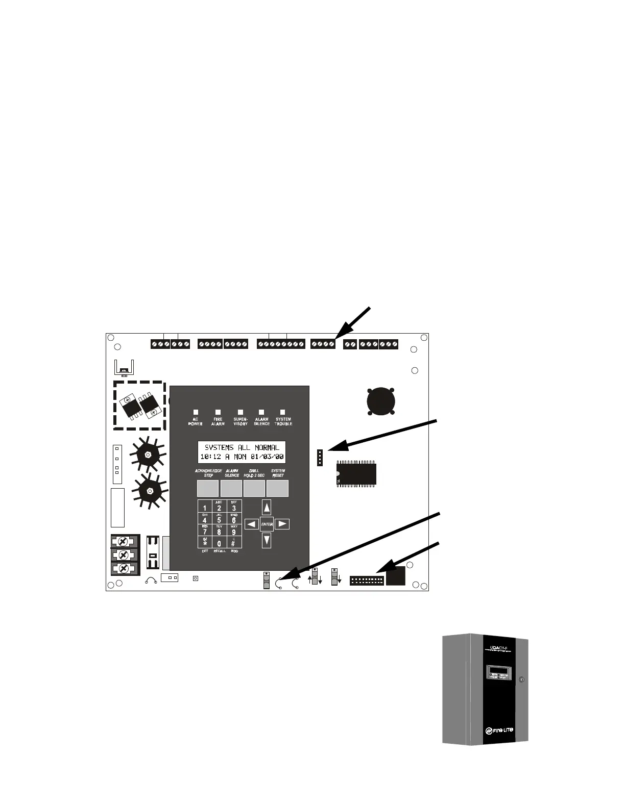
2.8 Optional Modules
The MS-9200 supports option modules using connectors J6, and J16 on the main circuit board. There are two
optional modules available for the MS-9200:
• RTM-8F Relay/transmitter Module
• UDACT-F Universal Digital Alarm Communicator/Transmitter
Note that older versions of the MS-9200 main circuit board do not have connector TB7 which allows connection of a
PC, printer or Terminal Mode annunciator. These boards will have a plug-in connector J11 which supports:
• PIM-24 Printer/PC Interface Module
• DIM-485 Display Interface Module (for use with LCD-40 Series annunciators)
Jumper JP4 must be cut before installation of the RTM-8F module to enable module placement supervision. Note
that devices connected to the EIA-485 connectors, the EIA-232 connector or SLC loop may be protected from volt-
age transients by using one of the UL listed compatible surge suppressors listed in the Fire•Lite Device Compatibility
Document.
2.8.1 UDACT-F Universal Digital Alarm Communicator/Transmitter
The UDACT-F transmits system status to UL listed Central Station receivers via
the public switched telephone network. It is capable of reporting up to 56 soft-
ware zones or up to 198 addressable points. The UDACT-F may be mounted
directly to the MS-9200 main circuit board or remotely in a UBS-1F or ABS-8RF
enclosure. The MS-9200 requires software P/N 73580 or higher to support the
UDACT-F. For additional information, refer to the UDACT-F Manual.
24V UNREG 24V NONRS 24 V RST
BELL 2 POWER
BELL 1 POWER
SUPV ALARM TROUB LE PC/PRI NTER TERM C OMM
GND FAULT
DISABLE
TRANSFORMER 1
TRANSFORMER 2
- +
BATTERY
RS-232
PC/PRINTER
RS-485
TERM. MODE
TROUBLE
+ - + - + -
B+ A + A- B-
B+ A + A- B-
NO C NO NC C NO NC C
A B B+ A+ B - A-
1 COMM 2
ACS
SHI ELD SL C SLC
OUT+ IN+ OUT- IN-
T
B
4
T
B
2
T
B
1
T
B
3
T
B
7
T
B
5
T
B
6
J16
J6
JP3
JP1
CAUTION
HIGH VOLTAG E
J3
TB8
J19
J17
JP4
SW1
SW3
SW2
CAUTION!
HIGH VOLTAGE
GNDFAULT
FIGURE 2-8:
Option Module Locations
PC/Printer Interface
J16 accepts UDACT-F
Cut JP4 for RTM-8F supervision
J6 accepts RTM-8F
9200bord.cdr
FIGURE 2-9:
UBS-1F