Document #51003 Rev.E 01/11/02 P/N 51003:E 73
ACS and LDM Series Wiring
Appendix D ACS and LDM Series Wiring
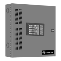
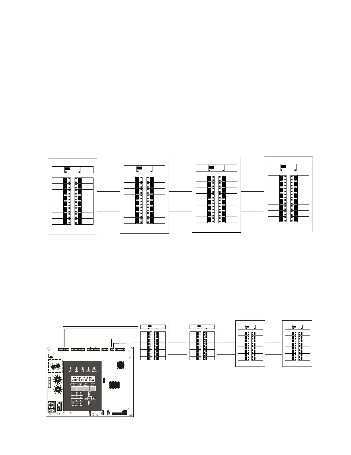
The following illustrations show the various configurations which may be wired utilizing ACS Series Annunciators.
LDM Series Annunciators may be used in a similar manner. All illustrations show power supplied to annunciators by
the MS-9200. For system applications requiring greater than the 300 mA of nonresettable power the MS-9200 can
supply, use the Fire•Lite FCPS-24F/E Field Charger Power Supply.
The following figure shows a configuration which provides 56 zones of alarm and trouble indications, remote
Acknowledge/Step, Alarm Silence, Drill and System Reset keys, System Supervisory, AC Fail, and Trouble indica-
tions. Use AKS-1F keyswitch to prevent unauthorized actuation of control switches. Refer to the AFM Manual for
further details.
24V UNREG 24V NONRS 24V RST
BELL 2 POWER
BELL 1 POWER
SUPV ALARM TROUB LE PC/PRINTE R TERM CO MM
GND FAULT
DISABLE
TRANSFORMER 1
TRANSFORMER 2
- +
BATTERY
RS-232
PC/PRINTER
RS-485
TERM. MO DE
TROUBLE
+ - + - + -
B+ A+ A- B-
B+ A+ A- B-
NO C NO NC C NO NC C
A B B+ A+ B- A-
1 COMM 2
ACS
SHIELD SLC SLC
OUT+ IN+ OUT- IN-
T
B
4
T
B
2
T
B
1
T
B
3
T
B
7
T
B
5
T
B
6
J16
J6
JP3
JP1
CAUTION
HI GH V OLTAG E
J3
TB8
J19
J17
JP4
SW1
SW3
SW2
CAUTION!
HIGH VOLTAGE
GNDFAULT
ACM-16ATF AEM-16ATF AEM-16ATF
AEM-16ATF
Ribbon
Cable
Ribbon
Cable
Ribbon
Cable
8 Zones (Alarm & Trouble)
4 switches IACK, SIL,
DRILL, RESET), System
Trouble LED, On-Line/Off-
Line Power LED, Piezo
sounder
16 Zone (Alarm & Trouble)
16 Zone (Alarm & Trouble)
16 Zone (Alarm & Trouble)
Ribbon
Cable
Ribbon
Cable
Ribbon
Cable
Annunciator Power - 12 to 18 AWG
2-wire EIA-485 circuit -
max. 6,000 ft. @ 16 AWG
MS-9200
Data Communication Port:
EIA-485 @ 20K Baud