Document #51003 Rev.E 01/11/02 P/N 51003:E 33
Optional Modules
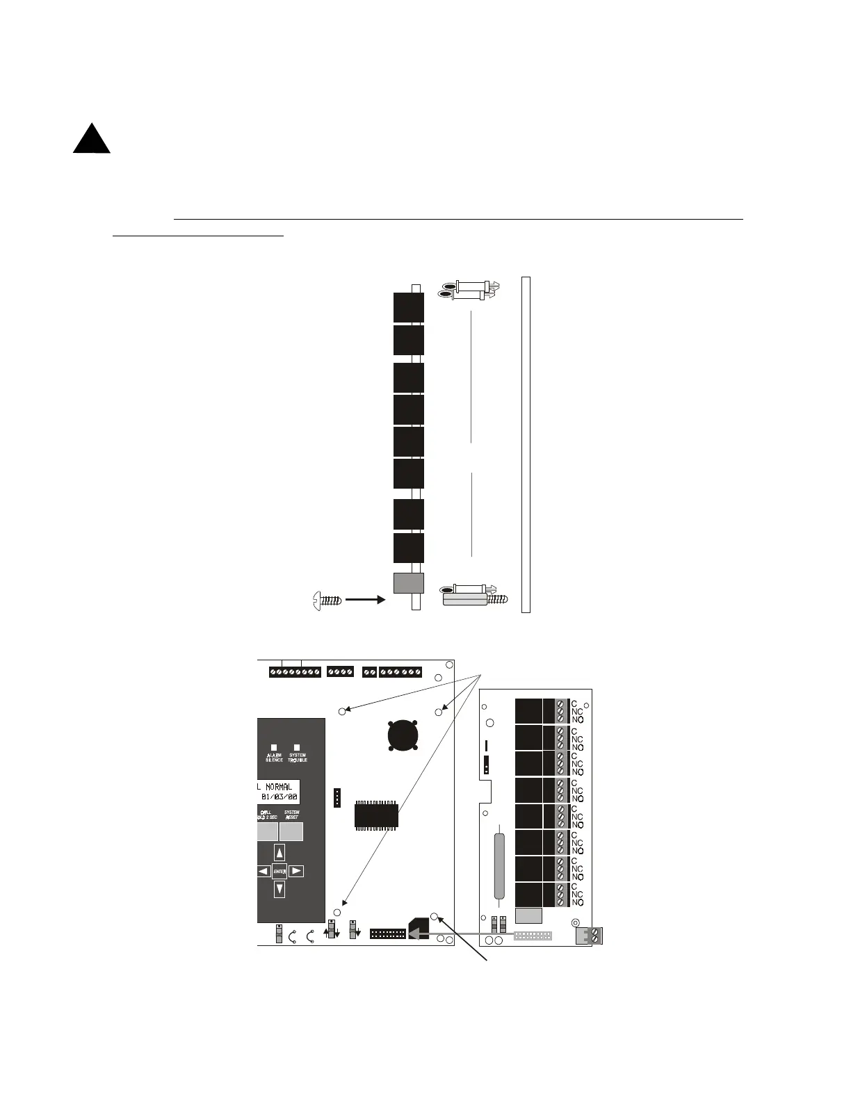
2.8.3 RTM-8F Option Module Installation
WARNING! Disconnect all sources of power (AC and DC) before installing or removing any modules or wiring
Insert the three supplied nylon standoffs into the holes located on the right-side edge of the MS-9200 main circuit
board. Insert the supplied metal standoff on the lower-right corner. Carefully align the pins of J6 on the main circuit
board with connector J1 on the RTM-8F option board. Press firmly on the RTM-8F until it locks in place on the
standoffs. Be certain to tighten the screw into the metal standoff on the lower-right corner. This is critical to the
RTM-8F transient protection.
Affix the terminal identification labels provided with the option module.
!
SUPV AL ARM T ROU BLE PC/ PRINT ER T ERM COMM
GND FAULT
DISABLE
RS-232
PC/PRINTER
RS-485
TERM. MODE
TROUBLE
NO C NO NC C NO NC C
A B B + A+ B- A-
1 COMM 2
ACS SHI ELD SL C SL C
OUT+ IN+ OUT- IN-
T
B
3
T
B
7
T
B
5
T
B
6
J16
J6
JP3
JP4
SW1
SW3
SW2
FIGURE 2-15:
RTM-8F Module Installation
RTM-8F
Main Circuit Board
¾" aluminum standoff with nut
required for transient protection
¾" nylon standoffs
Use metal screw and standoff here
Main Circuit Board
insert here
RTM-8F Option Module
Standoffs
rtm8soff.cdr
9200rtm8.cdr