,QVWDOODWLRQ 2SWLRQDO0RGXOH,QVWDOODWLRQ
068'31$
0RGXOH,QVWDOODWLRQRQ%5.7
7KHIROORZLQJPRGXOHVFDQEHLQVWDOOHGLQVLGHWKH068'FDELQHWXVLQJWKH
%5.78QLYHUVDO%UDFNHW
✓ UDACT-F Digital Alarm Communicator/Transmitter - installs at standoff
location (A)
✓ ACM-8RF Annunciator Control Module (Relay) - installs at standoff location
(A)
5HIHUWRWKHDSSURSULDWHPRGXOHPDQXDOIRUGHWDLOHGLQIRUPDWLRQRQPRGXOH
RSHUDWLRQDQGZLULQJ
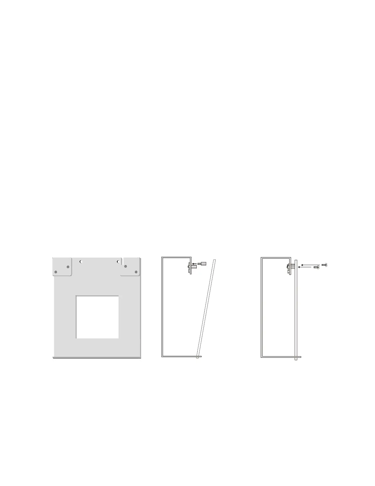
1. Install the two supplied standoffs in location (A) as indicated in Step 1 of the
following illustration
2. Position the module bottom in the slot located in the bottom of the BRKT-9600
as indicated in Step 2 of the following illustration
3. Secure the module to the standoffs installed in the top of the BRKT-9600 with
two mounting screws as indicated in Step 3 of the following illustration
4. Refer to the appropriate module manual for detailed information on wiring the
module for power, communication, etc.
5. Install a maximum of two 12 Amp Hour batteries with the orientation illustrated
in Figure 2.7. Larger batteries require a separate UL listed battery box
1RWH'RQRWEULQJZLULQJRUFRQGXLWLQWRWKHERWWRPRIWKHFDELQHWIRUWKLV
DSSOLFDWLRQ
Figure 2.8 BRKT-9600 Module Installation Steps
Step 1
Step 2
Step 3
(A)
(A)
Slot
module
module
BRKT-9600
BRKT-9600 BRKT-9600
mounting
screws
standoffs
96brcksd.cdr
9600brkt.cdr