EQUIPMENT: FIRECLASS DUO -CEL WRITTEN BY: RKP
PUBLICATION: OM_FC_DUO-CEL_INST CHECKED BY: AP
ISSUE No. & DATE: 0 01/03/12
PAGE 3 of 29
1. Introduction
This document contains all the information
necessary for the installation, commissioning and
maintenance of the FIRECLASS DUO-CEL panel
and repeater.
Please read this manual fully before
commencing installation.
The following supporting documentation is also
available:
FIRECLASS DUO-CEL
Sales Literature
FIRECLASS DUO-CEL Panel Application Guide
FIRECLASS DUO-CEL
User Manual
FIRECLASS DUO-CEL Log Book
References are made throughout this document to
“Fire Signal Output”. This is an output used to send
a common fire warning signal to a remote fire
monitoring station. It should not be used for any
other purpose.
1.1 Panel Identification
The DUO-CEL panel & Repeater type can be
identified from the Part Number on the side of the
enclosure (see section 13. for location details).
The table below shows the part numbers.
8 Zone Repeater – C/W PSE
2. Panel Circuit Details
2.1 Auxiliary Supply
An auxiliary supply output is available to power the
repeaters and other external field equipment from
the panel. This voltage is nominally 27.15Vdc but
varies during mains-failed conditions, depending on
battery voltage.
The output is electronically fused and fuse
activation will be indicated as Fuse Failed on the
panel display. The fuse can be reset after removal
of the fault by operating the Reset button on the
display.
The auxiliary supply terminals are labelled AUX
0.25A 24V and 0V.
An additional UNFUSED 24V output is provided on
repeaters for connection to additional DC powered
repeaters.
Note: If equipment draws current from the
auxiliary supply during the mains-failed
condition this must be included in the battery
capacity calculations.
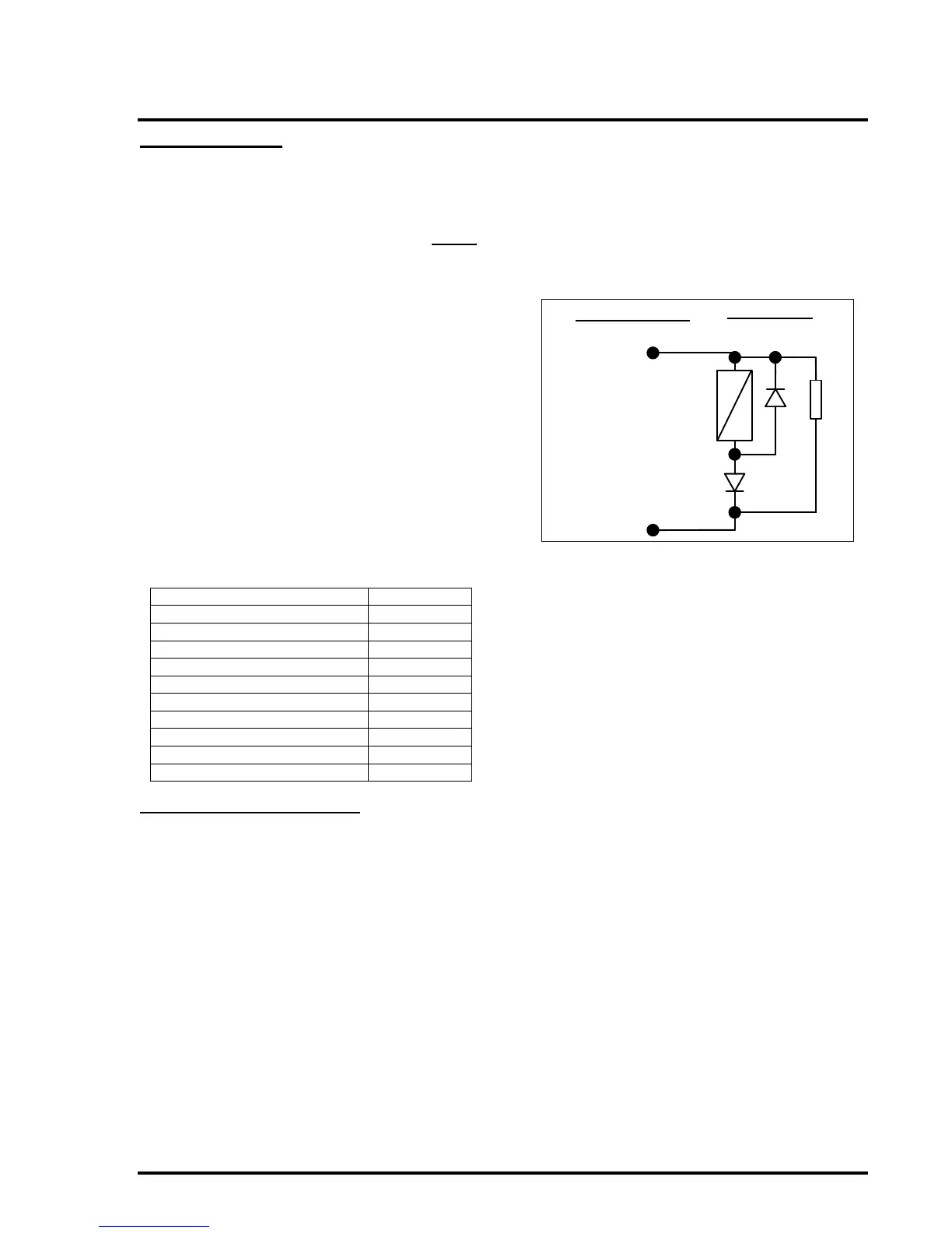
2.2 Fire Signal Output
The Fire Signal output is fault-monitored in the non-
energised condition. It is designed to operate a
signalling relay at the routing equipment. The Relay
coil must be polarised and suppressed, because
the 10k end-of-line device is reverse-polarity
monitored for open & short circuit faults. See Figure
1 for details.
Figure 1 – Fire Signal Output Connections
+
-
Field Wiring
Panel Terminals
Output conditions:
Quiescent: -5V DC
[open circuit voltage]
Active [fire]: 24V
[nominal]
DIODE
1N4002
10k
EOL
DIODE
1N4002
2.3 Fire Relay Output
The Fire Relay output is a single pole relay with
volt-free change-over contacts. The relay is
normally de-energised and energises for any fire
alarm condition. The relay remains energised until
panel reset. This relay will not energise if zone 1 is
configured as non-latching and only zone 1 is in
alarm. See Figure 2 for details.
2.4 Fault Relay Output
The Fault Relay output is a single pole relay with
volt-free change-over contacts. The relay is fail-safe
and is therefore normally energised, de-energising
for any faults. The marking on the control board
terminals is for the energised condition. See Figure
2 for details.
NOTE: