Note:
To prevent unauthorised operation of the
system, any manually operated function must
be operated by a key-switch. The key to the
switch should be held with the panel’s access
control key.
For the SILENCE ALARMS and RESET
functions, the Keyswitch should be spring-
biased so that it automatically returns to the off
position when released.
2.6 Open Collector Outputs
Three open collector outputs are provided:
1. Disabled (DIS.)
2. Evacuate (EVAC.)
3. Buzzer Active (BUZ.)
They are referred to as „open collector‟ because
each output is connected to the open collector pin
of a transistor.
In the deactivated state, each open collector output
is floating and is effectively open circuit. When the
output is activated, the transistor allows current to
flow from the open collector pin down to 0V. Each
output is able to sink 50mA when active. Higher
currents will damage the transistor driver.
If the output is used to drive a relay then a
suppression diode should be used across the relay
coil to avoid damaging the output driver circuit.
2.6.1 Disabled Output
The Disabled output is activated when any
disablements exist on the panel. The only
exceptions are Buzzer Disable and Earth Fault
Disable, both of which produce no indications on
the panel.
2.6.2 Evacuate Output
The Evacuate output is activated when the panel is
in the Evacuate state, either due to the button on
the display or due to the Remote Control input.
2.6.3 Buzzer Active Output
The Buzzer Active output duplicates the panel
buzzer for alarm and fault conditions. It does not
operate for button presses.
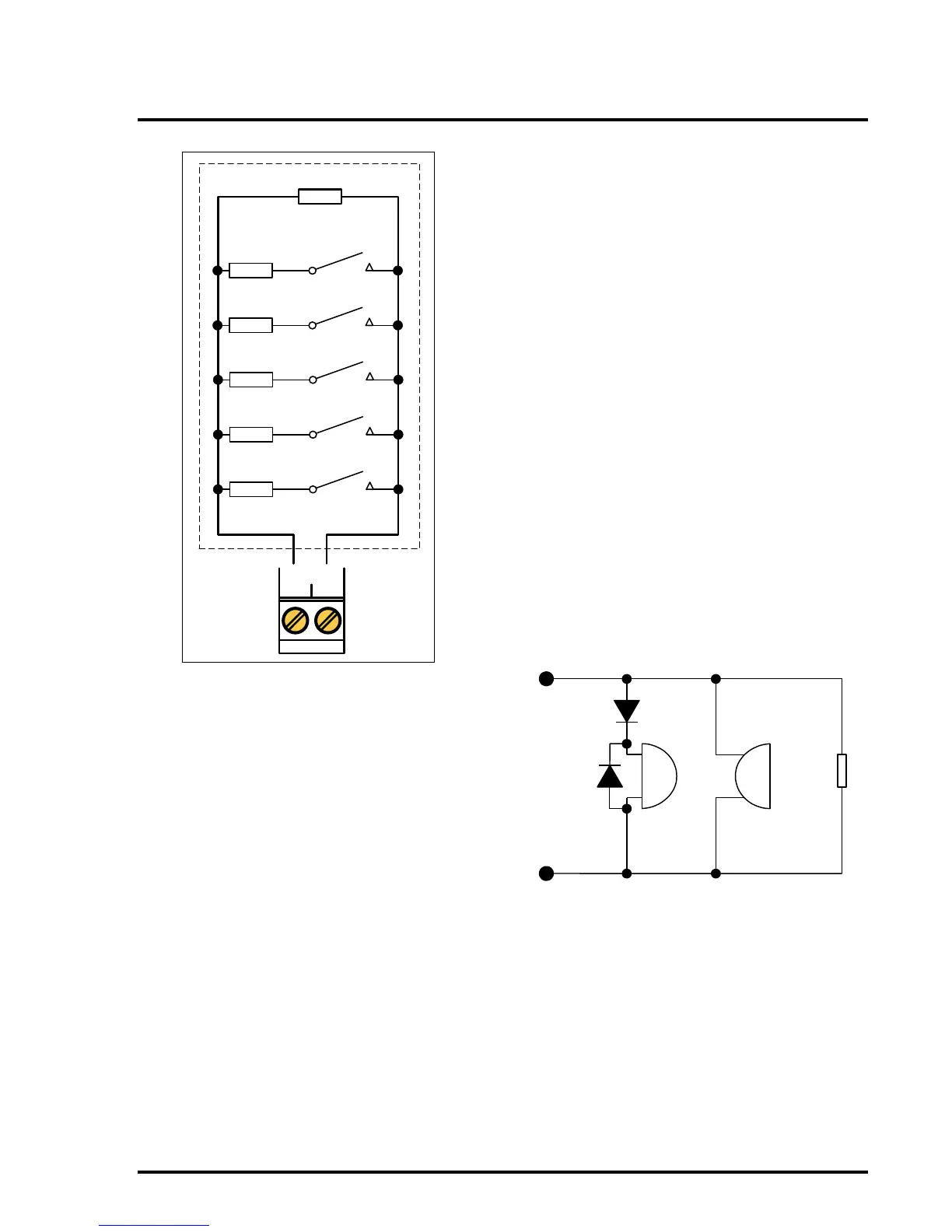
2.7 Sounder Circuits
The panel has up to 4 standard sounder circuits,
each rated at 0.5 Amps (not including twin-wire
sounders). The circuits are reverse polarity
monitored for open and short circuit faults. All
connected field devices must be polarised to allow
correct fault monitoring. To prevent damage to the
control panel, any solenoid devices such as bells
must also have a suppression diode fitted as shown
in Figure 4.
The circuit must be terminated with a 10K end of
line resistor.
Figure 4 – Alarm circuit configuration
2.8 Electrical Design of Detection Zones
To allow the panel to correctly monitor for fault
conditions, the wiring for each zone must be
installed as a continuous pair with no spurs or tees.
The end-of-line monitoring device will depend on
the zone configuration of the panel. Correct polarity
must be strictly observed throughout.
2.8.1 Standard Panel Default Zone
Configuration
The Default Zone Configuration (factory Default) on
the standard panel uses active fault monitoring,
with a 10uF capacitor as the EOL device. This
allows the maximum number of detectors to be
used (up to 32 per zone) and maintains line