EQUIPMENT: FIRECLASS DUO -CEL WRITTEN BY: RKP
PUBLICATION: OM_FC_DUO-CEL_INST CHECKED BY: AP
ISSUE No. & DATE: 0 01/03/12
PAGE 15 of 29
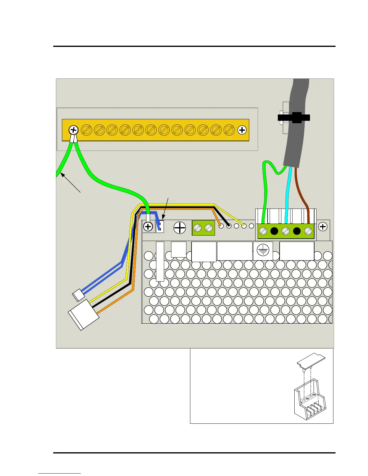
Figure 12 – BAQ35T24 1.5A Power Supply Connections
COVER PLATE (SUPPLIED IN THE
SPARES KIT) TO BE MOUNTED INTO
THE TWO EMPTY SCREW HOLES IN
THE PSU TERMINAL BLOCK
TB2
VR1
NTC
+V
GND
B-
L
B+
Power
Connection to
Control Board
Incoming Mains
Cable
Secured with a
cable tie to the
backbox
Earth Wire to
EARTH bar
+V
ADJ
- +
DC OUT
27V
1.5A Power
Supply Unit
230VAC IN
N L
THERMISTOR
DC OUT
TO PANEL
Power
Connection to
Control Board
Thermistor
Connection to
Control Board
Leave the
Earth wire 3cm
longer than the
Live & Neutral
wires
Negative
Temperature
Coefficient
Thermistor Input
Connector.
Earth Wire to
Control Board
Mounting
Screw
NOTE: The black wire may be connected to
(B-) instead of (GND) on the PSU. This is
quite normal and does not affect the
operation of the PSU in any way.