EQUIPMENT: FIRECLASS DUO -CEL WRITTEN BY: RKP
PUBLICATION: OM_FC_DUO-CEL_INST CHECKED BY: AP
ISSUE No. & DATE: 0 01/03/12
PAGE 23 of 29
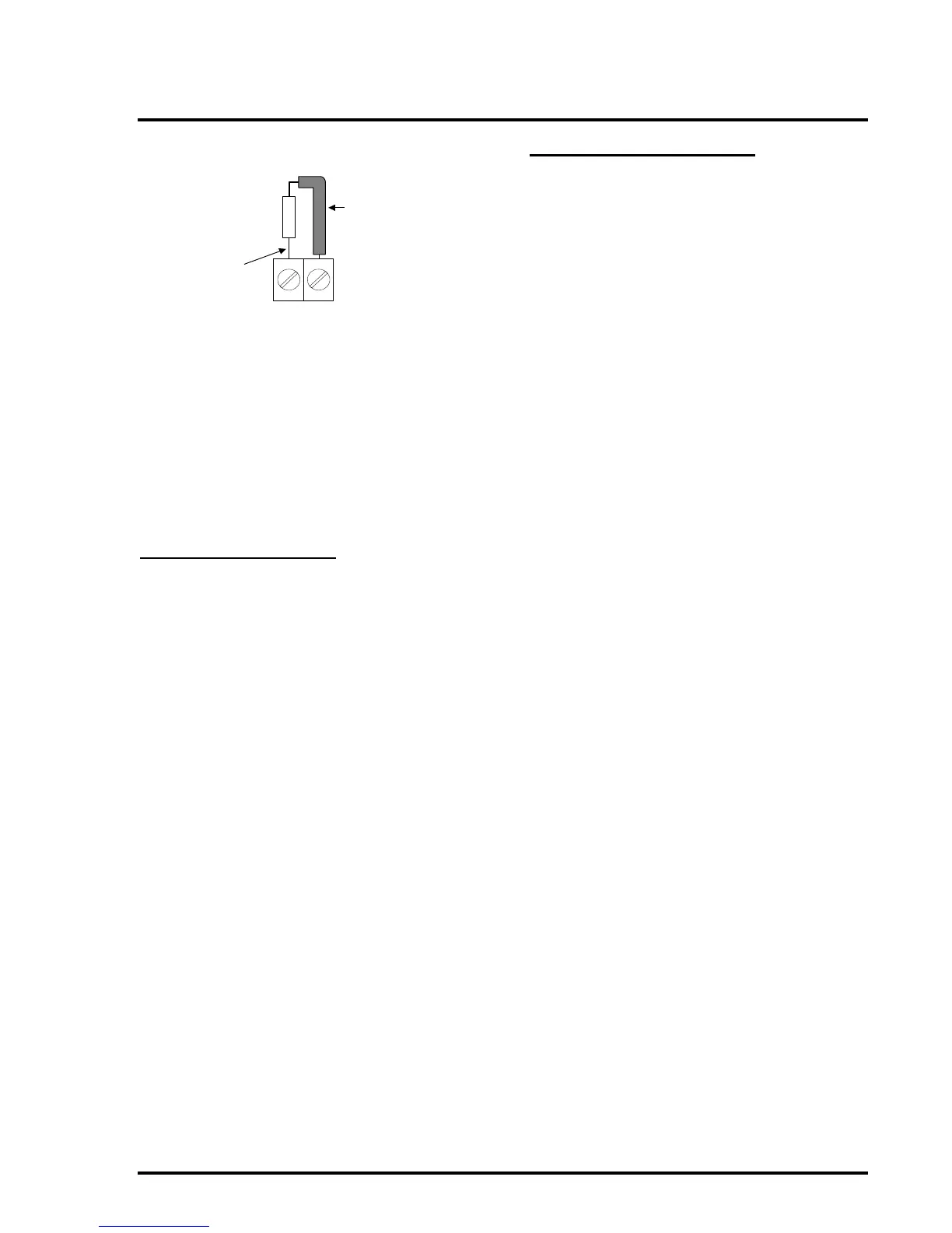
have insulating sleeving placed on the leads for
safety.
7.9 Site Configuration
Once the panel and repeaters have been installed
and tested for basic operation, any site-specific
settings can be applied via the DIL switches.
Each of the selected options should be tested to
ensure the panel operates as required.
Record all settings in the log book for future
reference.
8. System Handover
Once the panel and repeaters have been installed
and fully tested in accordance with the site specific
requirements, the front cover of the enclosure can
be attached to the panel and repeaters.
The ACCESS keys should be removed from the
panel and repeaters and handed over to the site‟s
designated Responsible Person.
Note: In order to comply strictly with the
requirements of EN54-4:1998 Clause 6.2.1 (Power
Supply Equipment Enclosure shall meet at least
classification IP30 of EN 60529:1991), the
Keyswitch hole must be blocked when not in use,
by inserting the rubber bung supplied. This is
because the hole is greater than 2.5mm in
diameter.
All authorised users must be given adequate
instruction and training in the operation of the
system.
9. System Maintenance
System maintenance details can be found in the
logbook.