ET Valve
Instruction Manual
Form 5081
June 2002
7
Table 3. Body-to-Bonnet Bolt Torque Guidelines
VALVE SIZE, INCHES BOLT TORQUES
(1)
SA193-B7, SA193-B8M
(3)
SA193-B8M
(2)
Design ET Design EAT
Nm Lbfft Nm Lbfft
1-1/4 or less 1 129 95 64 47
1-1/2, 1-1/2 x 1, 2, or 2 x 1 2 or 2 x 1 96 71 45 33
2-1/2 or 2-1/2 x 1-1/2 3 or 3 x 1-1/2 129 95 64 47
3, 3 x 2, or 3 x 2-1/2 4 or 4 x 2 169 125 88 65
4, 4 x 2-1/2, or 4 x 3 6 or 6 x 2-1/2 271 200 156 115
6 ––– 549 405 366 270
8 ––– 746 550 529 390
1. Determined from laboratory tests.
2. SA193-B8M annealed.
3. SA193-B8M strain hardened.
screws completely and carefully lift the bonnet off
the valve.
5. Remove the locknut and separate the valve plug
and stem from the bonnet. Set the parts on a
protective surface to prevent damage to gasket or
seating surfaces.
6. Remove the bonnet gasket (key 10, figure 16, 17,
or 20) and cover the opening in the valve to protect
the gasket surface and prevent foreign material from
getting into the valve body cavity.
7. Remove the packing flange nuts, packing flange,
upper wiper, and packing follower (keys 5, 3, 12, and
13, figure 14). Carefully push out all the remaining
packing parts from the valve side of the bonnet using
a rounded rod or other tool that will not scratch the
packing box wall. Clean the packing box and the
metal packing parts.
8. Inspect the valve stem threads and packing box
surfaces for any sharp edges which might cut the
packing. Scratches or burrs could cause packing box
leakage or damage to the new packing. If the
surface condition cannot be improved by light
sanding, replace the damaged parts by following the
appropriate steps in the Trim Maintenance
procedure.
9. Remove the covering protecting the valve body
cavity and install a new bonnet gasket (key 10,
figure 16, 17, or 20), making sure the gasket seating
surfaces are clean and smooth. Then slide the
bonnet over the stem and onto the stud bolts (key
15, figure 16, 17, or 20) or onto the valve body cavity
if cap screws (not shown) will be used instead.
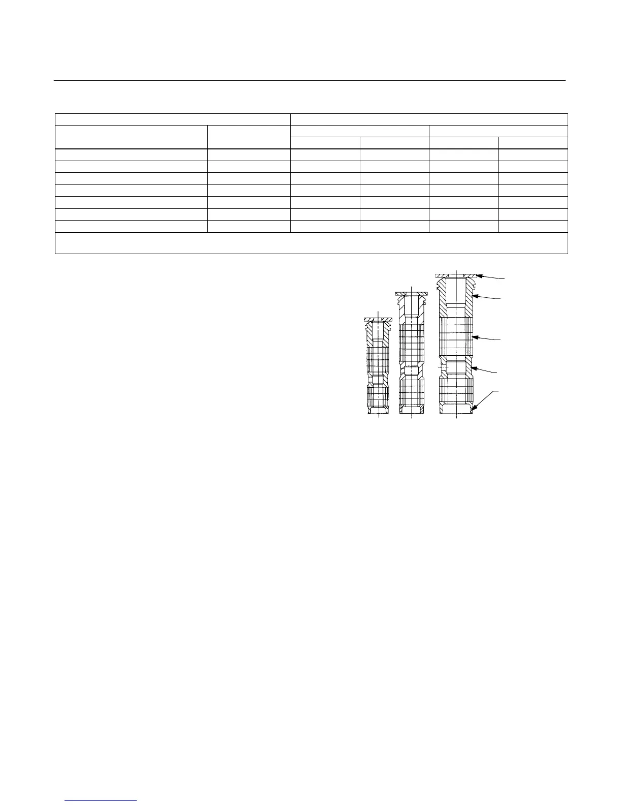
Figure 4. Detail of PTFE/Composition Packing Arrangements
for Plain and Extension Bonnets
UPPER WIPER
(KEY 12)
PACKING
FOLLOWER (KEY 13)
LANTERN RING
(KEY 8)
PACKING BOX
RING (KEY 11)
PACKING RING
(KEY 7)
9.5 mm
(3/8 INCH)
STEM
12.7 mm
(1/2 INCH)
STEM
19.1, 25.4, OR
31.8 mm
(3/4, 1, OR
1Ć1/4 INCH)
STEM
12A8188-A
12A7815-A
12A8173-A
A2619-1 / IL
Note
Proper performance of the bolting
procedures in step 10 compresses the
spiral wound gasket (key 12, figure 16
or 17) or load ring (key 26, figure 20)
enough to both load and seal the seat
ring gasket (key 13, figure 16, 17 or 20).
It also compresses the outer edge of
the bonnet gasket (key 10, figure 16
through 20) enough to seal the
body-to-bonnet joint.
The proper bolting procedures in step
10 include—but are not limited
to—ensuring that bolting threads are
clean, and evenly tightening the cap
screws, or the nuts onto the studs, in a
crisscross pattern. Tightening one cap
screw or nut may loosen an adjacent