6 Installation of FLUXUS ADM 8027 FLUXUS ADM 8027, F801, ADM 8127B
UMFLUXUS_F8V4-6-1EN, 2018-10-10 29
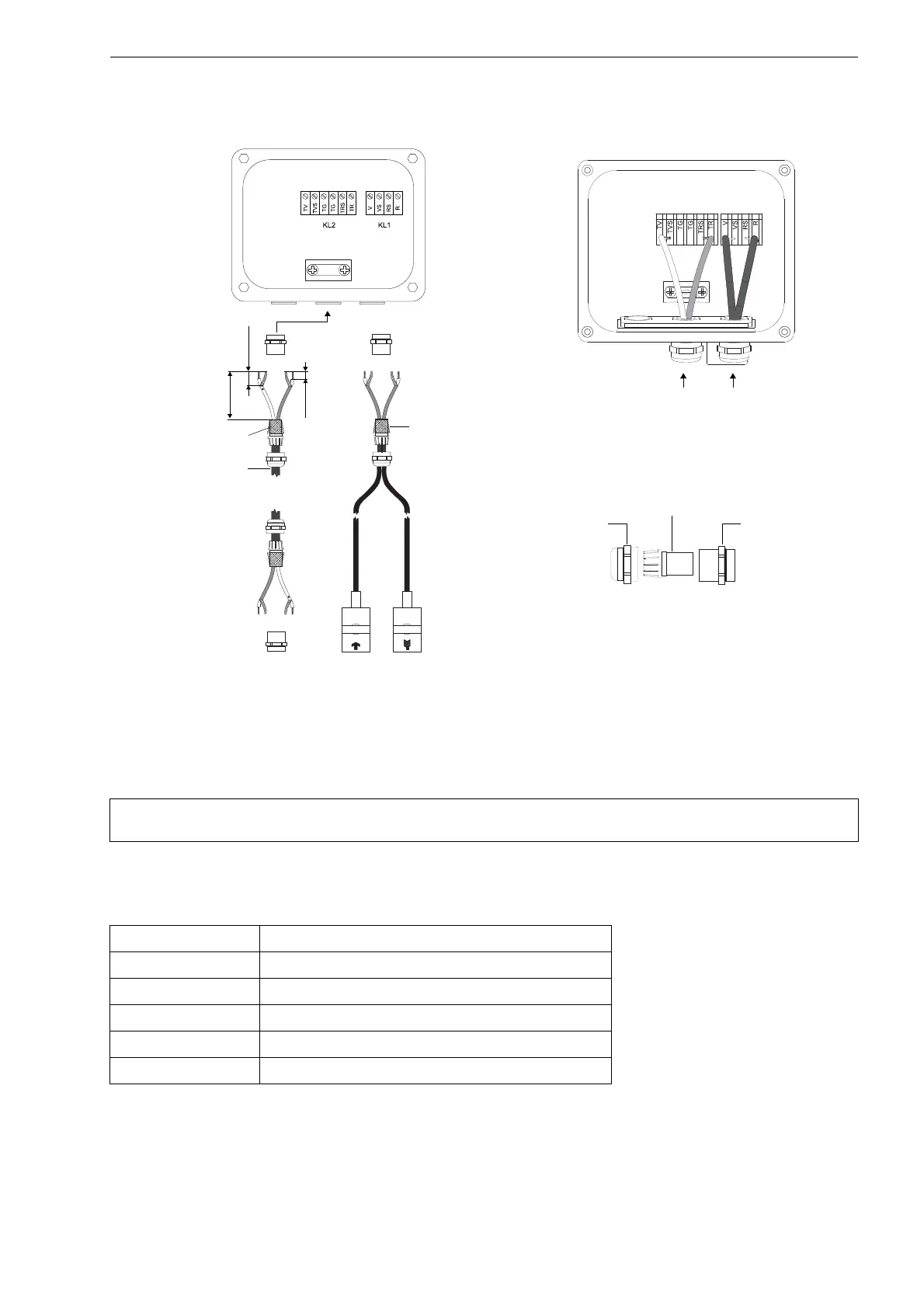
• Prepare the extension cable.
• Cut the external shield and brush it back over the compression part.
• Screw the gasket ring side of the basic part into the junction box.
• Insert the extension cable into the junction box.
• Fix the cable gland by screwing the cap nut onto the basic part.
• Connect the extension cable to the terminals of the transmitter (see Fig. 6.7 and Tab. 6.2).
Fig. 6.7: Connection of the extension and transducer cable to the junction box JB01
Attention! For good high frequency shielding, it is important to ensure good electrical contact between the exter-
nal shield and the cap nut (and the junction box).
Tab. 6.2: Terminal assignment (extension cable, KL2)
terminal connection
TV white or marked cable (core)
TVS white or marked cable (internal shield)
TRS brown cable (internal shield)
TR brown cable (core)
cable gland external shield
100 mm
20 mm
10 mm
external shield,
brushed back
extension cable
extension cable transducer cable
cap nut
compression part
basic part
cable gland
external shield,
brushed back
 Loading...


