7 Connection FLUXUS F70x
UMFLUXUS_F7V4-6-2EN, 2017-10-01 63
FLUXUS F709
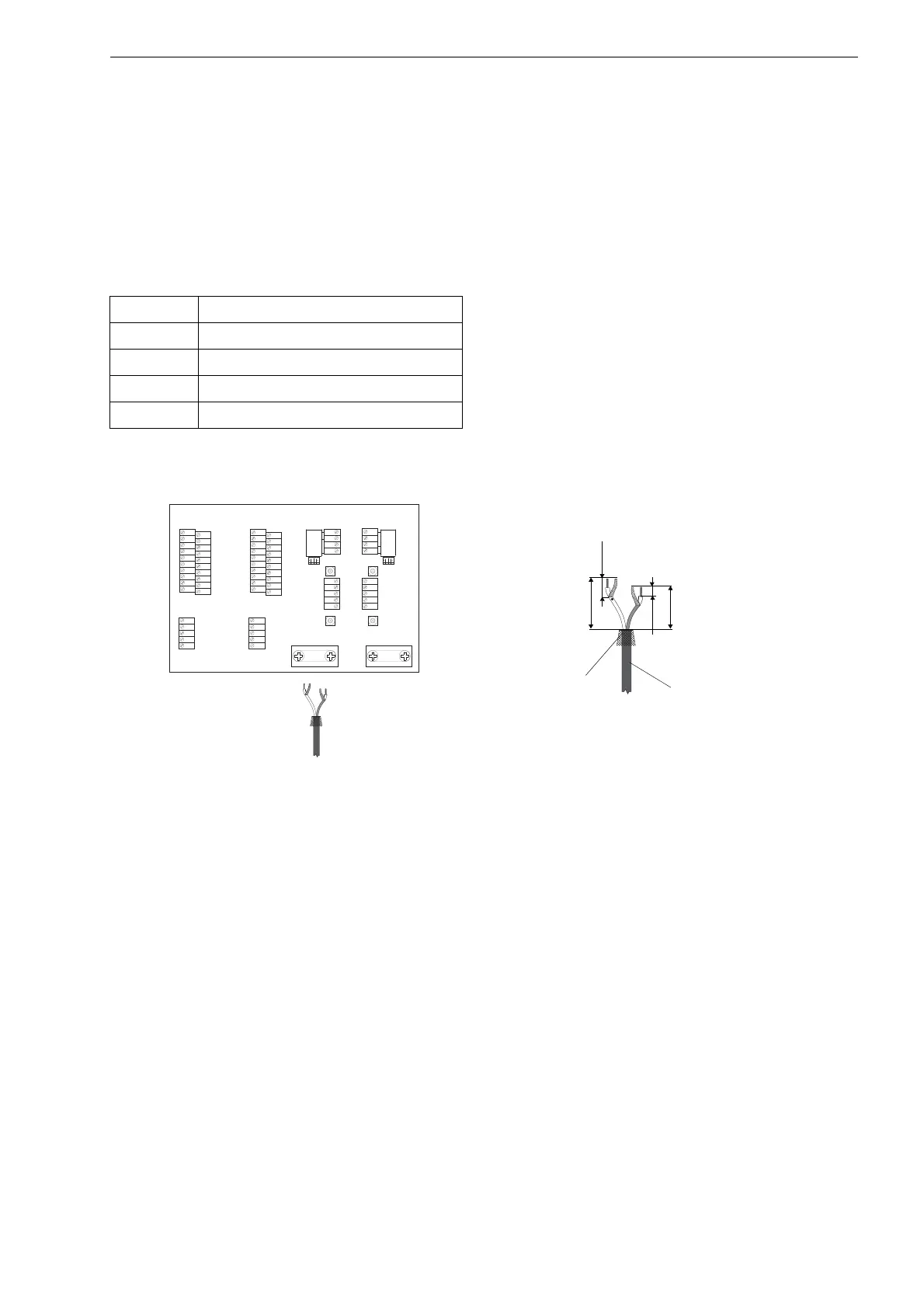
• Prepare the extension cable. Cut the external shield and brush it back (see Fig. 7.16).
• Push the extension cable through the shield terminal to terminal strip KL6 for measuring channel A and to terminal strip
KL8 for measuring channel B.
• Pull the extension cable back until the brushed back outer shield is below the shield terminal.
• Fix the extension cable and the external shield to the shield terminal.
• Connect the extension cable to the terminals of the transmitter (see Fig. 7.4, Fig. 7.16 and Tab. 7.7).
Tab. 7.7: Terminal assignment
terminal connection
AV white or marked cable (core)
AVS white or marked cable (shield)
ARS brown cable (shield)
AR brown cable (core)
Fig. 7.16: Connection of the extension cable with plastic cable jacket
and stripped cable ends to the transmitter FLUXUS F709
K L 4K L 2
X 6 A R X 8 B R
A R S
A R
S
B R
4 A +
4 B -
4 2
4 3
4 1
L +
L -
N
L 1
P E
60 mm
20 mm
10 mm
extension cable
external shield,
brushed back
K L 7
K L 5
K L 3
K L 1
X 7
K L 4K L 2
X 6 A V
X 8 B V
X 6 A R X 8 B R
X 5
BA
K L 6
K L 8
C H A N N E L
S A 3
S A 1
S A 2
S A 4
S B 3
S B 1
S B 2
S B 4
A V S
A V
A R S
A G N
A R
B V S
B V
B R S
B G N
B R
4 A +
4 B -
4 2
4 3
4 1
L +
L -
N
L 1
P E
P 6 a
P 7 a
P 7 +
P 5 a
P 6 +
P 2 +
P 5 +
P 1 +
P 3 +
P 4 +
P 6 b
P 7 b
P 7 -
P 5 b
P 6 -
P 2 -
P 5 -
P 1 -
P 3 -
P 4 -
T 4 A
T 4 B
T 3 B
S 3
T 3 A
T 1 B
T 2 B
T 1 A
S 1
T 2 A
T 4 a
T 4 b
T 3 b
S 4
T 3 a
T 1 b
T 2 b
T 1 a
S 2
T 2 a
 Loading...


