Do you have a question about the Flintec FT-13 and is the answer not in the manual?
Lists the main capabilities and specifications of the FT-13 weighing controller.
Details the optional interfaces and power inputs for the FT-13 weighing controller.
Provides detailed technical data including accuracy, display, A/D converter, and load cells.
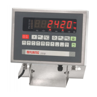
Illustrates the physical dimensions for both stainless steel and panel type housings.
Guides on selecting a safe operating location and avoiding electrical noise.
Details power supply, grounding, load cell, and digital I/O connections.
Explains wiring for 6-wire and 4-wire load cells and input resistance requirements.
Details the pinout and function of digital inputs and outputs for filling programmes.
Outlines the steps for initial setup, calibration, and peripheral configuration.
Explains the function of the weight display and status LEDs on the front panel.
Details the function of each key on the FT-13 front panel.
Describes how to activate/deactivate the key lock function to prevent unauthorized access.
Explains basic operations and navigation within the setup and calibration menu.
Details the metrological data block and legal metrological records counter.
Covers parameters for filter settings, date, and time entries.
Defines basic setup parameters like approved status, resolution, and scale build.
Explains the procedures for zero and span calibration, including under load.
Introduces the 9 standard filling programmes and their typical applications.
Guides on setting up the filling system, selecting programmes, and performing tests.
Details the parameters and operation for various standard filling programmes.
Details the parameters and operation for Programme 0: Open Container Filling.
Explains parameters for bunghole container filling, including safety conditions.
Describes parameters for filling below the surface, including lift delay and emptying.
Details parameters for filling and emptying type 1, focusing on bag filling.
Explains parameters for tank/silo/hopper filling and discharging cycles.
Details parameters for weigh-in/weigh-out systems and sticky materials.
Covers filling and emptying type 2, including total limit value checks.
Explains modes for filling bags, including standing and hanging configurations.
Details operation for filling bags from a weighing hopper and bag catcher system.
Guides on entering target values, tolerances, and cut-off points for filling.
Explains how to enter and recall recipes, which are sets of filling parameters.
Covers the selection of filling programmes and definition of main filling parameters.
Lists and explains various error codes and their possible causes and solutions.
Provides a summary of communication capabilities and interface options.
Details standard and optional serial interfaces for data export and control.
Explains fast, continuous data export to peripheral devices.
Describes PC communication for uploading/downloading data via software.
Details how to output data after a filling cycle or using the print key.
Covers setup parameters for serial interfaces 1 and 2, including data format and baud rate.
Explains connecting the indicator via Ethernet TCP/IP or Modbus RTU.
Details the pin configuration of the RJ45 Ethernet connector and LED indicators.
Guides on setting up Ethernet network parameters using Ether X software.
Describes the data structure for Ethernet output based on selected data formats.
Details connecting the indicator to a PLC bus via Profibus DP V0 & V1.
Explains the pin configuration of the 9-pin D-Sub Profibus connector and status LEDs.
Covers connecting the indicator to a PLC bus via ProfiNet.
Details ProfiNet interface LEDs and the Ethernet connector pinout.
Guides on setting up ProfiNet network parameters using EtherX software.
Details connecting the indicator to a PLC bus via CANopen.
Explains the pin configuration of the 9-pin D-Sub CANopen connector and status LEDs.
Guides on setting up CANopen parameters, including data format and address.
Provides functions for checking and testing the instrument's operation.
Lists instrument and option serial numbers, and software revision numbers.
Covers printing all parameters and loading default parameters.
| Accuracy Class | III |
|---|---|
| Operating Temperature | -10°C to +40°C |
| Excitation Voltage | 5V DC |
| Load Cell Connection | 4 or 6 wire |
| Power Supply | 12-24V DC |
| Protection Class | IP65 |
| Divisions | 10000 |
| Display | LCD |
| Serial Interface | RS232 |
| Output | Analog, Digital |