FT-13 Technical Manual, Rev. 1.40 March 2013
8.7 CANopen Option
Indicators which are equipped with the CANopen option can be connected to a PLC bus as described below.
Automatic (10 kbps to 12 Mbps)
Weight data will be updated each 40 ms
8.7.1 Electrical Connections
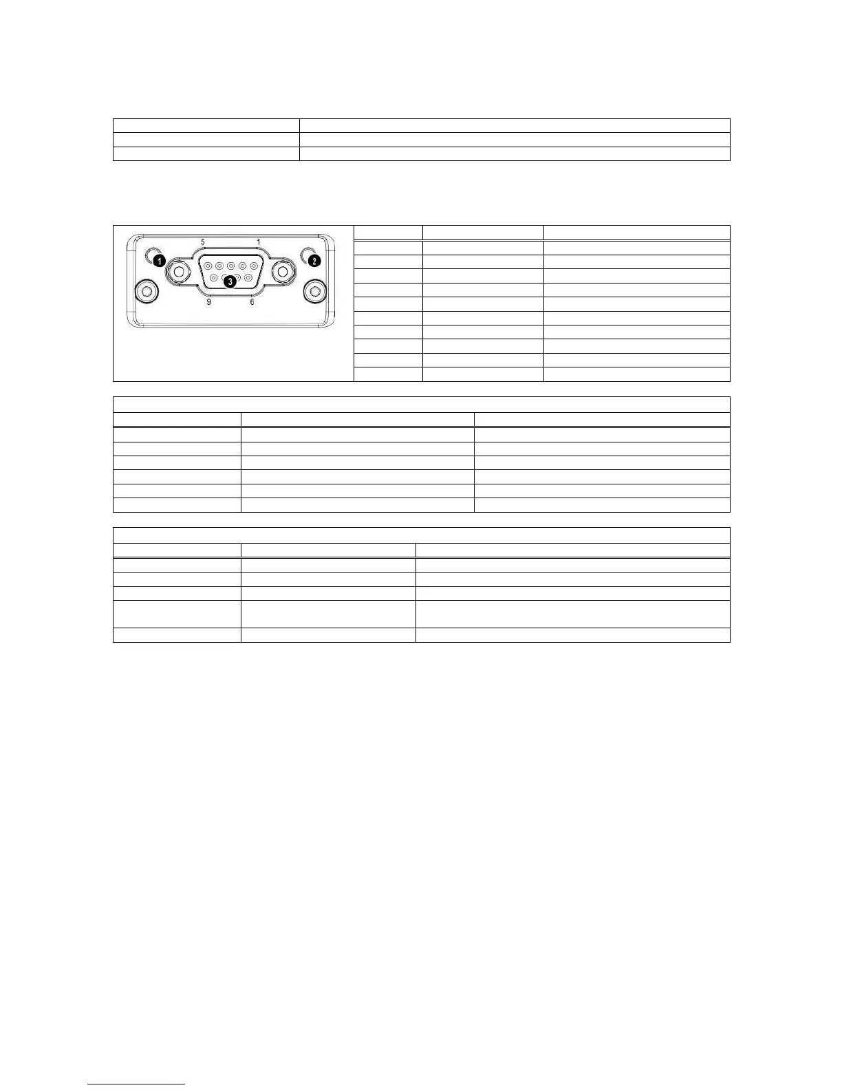
The pin configuration of the male 9-pol D-Sub ProfiNet connector (DB9M) is described in the table below:
1. Run LED
2. Error LED
3. CANopen Connector
No power or not initialized
Check for hardware damages
Auto baud rate detection in progress
No power or CANopen module is inizializing
Bus error counter reached or exceeded its warning limit
A guard (NMT slave or master) or heartbeat event has
occured
8.7.2 Setup
[0--] Interface Block
[03-] CANopen
This sub-block includes the parameters of the CANopen.
[034 X ] Data Format
0 : Signed 32 bit integer
1 : Signed 32 bit floating point
[035 XX] Address
The address of the instrument will be entered via numerical keypad. Value range is 1 to 127. After editing
the address it is required to restart the instrument.
After the setup of these parameters and the hardware connection as described above, the data interface can
be used as described in Appendix 5.
Important hint: During the setup the CANopen output (weight value and status bits) will not be updated.
8.7.3 Data Structure
See Appendix 5.