FT-13 Technical Manual, Rev. 1.40 March 2013
4.2.2 Standard Load Cell Connection
The load cell wiring should be made carefully before energizing to avoid damages to the weight indicator and
the load cells. The input resistance of the load cells that you want to connect should be more than 58 Ω.
The sense pins of the instrument should be connected. In 4-wire installations the sense and excitation pins with
the same polarity should be short circuited at the connector side.
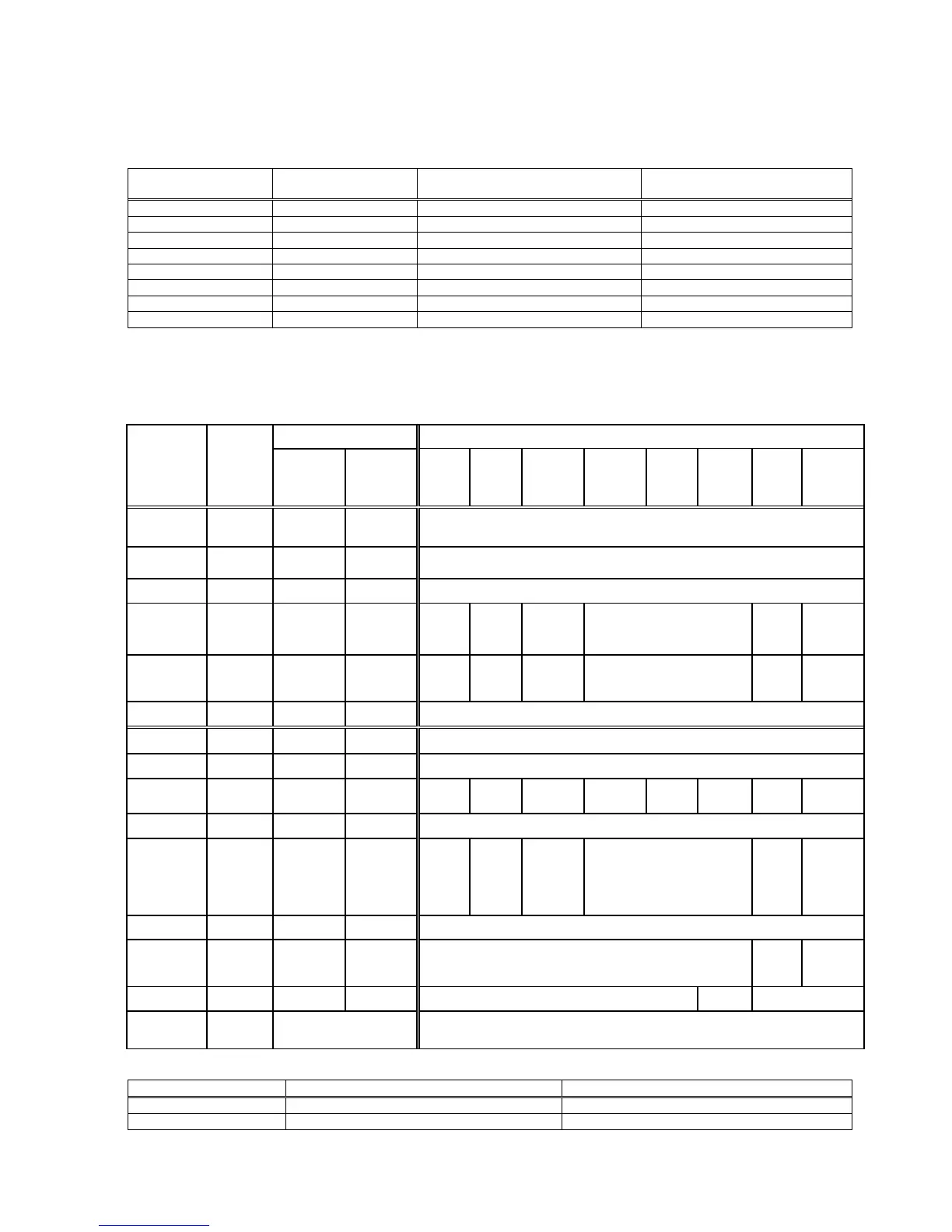
6-wire Load Cell
Connection
4-wire Load Cell
Connection
Pin no. for desk type & panel
type (D-Sub, 9-pin, female)
Pin no. for Stainless steel
housing (J12 connector)
4.2.3 Digital I/O Connections
FT-13 is equiped with a digital I/O board which provides 4 digital inputs and 8 digital outputs.
The meanings of the various I/O depend on the selected standard filling programme (see chapter 7).
Valve is
at middle
position
End of
Emptying
/
Vibration
output
P*: for Panel type housing; SS*: stainless steel housing
Max. 300 mA (sum of all 3 outputs)