FT-13 Technical Manual, Rev. 1.40 March 2013
8.4 Profibus Option
Indicators which are equipped with the Profibus option can be connected to a PLC bus as described below.
Automatic (96 kbit/s to 12 Mbit/s)
Weight data will be updated each 40 ms
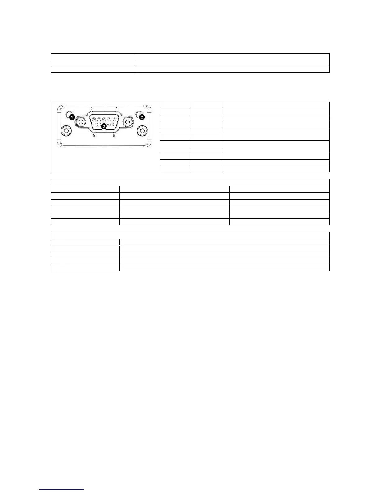
8.4.1 Electrical Connections
The pin configuration of the female 9-pol D-Sub Profibus connector (DB9F) is described in the table below:
1 Operation mode LED
2 Status LED
3 Profibus Connector
Positive RxD / TxD, RS485 level
Isolated +5V output for bus termination
Negative RxD / TxD, RS485 level
Bus cable shield, connected to Ground
PROFIBUS configuration error
No power or Profibus module is initialising
Initialized and diagnostic event is present
There is an exception error
8.5.2 Setup
[0--] Interface Block
[03-] Profibus
This sub-block includes the parameters of the Profibus port.
[032 X ] Data Format
0 : Signed 32 bit integer
1 : Signed 32 bit floating point
[033 XX] Address
The address of the instrument will be entered via numerical keypad. Value range is 1 to 126. After editing
the address it is required to restart the instrument.
The GDS file is available on a CD which is supplied together with the instrument.
After the setup of these parameters and the hardware connection as described above, the data interface can
be used as described in Appendix 4.
Important hint: During the setup the Profibus output (weight value and status bits) will not be updated.
8.5.3 Data Structure
See Appendix 4.