FT-13 Technical Manual, Rev. 1.40 March 2013
[023 XX] Address
You can define a device address between 1 and 99 by this parameter. Entry 0 no address.
[024 X] Serial Mode
0 : Serial Interface-2 operates as RS232C
1 : Serial Interface-2 operates as RS485
2 : Serial Interface-2 operates as 20 mA TTY Current Loop (not for stainless steel housing)
[025 X] Data Length and Parity
Note: The parameter [025] must be set to “0” for Modbus RTU output.
[026 X] Checksum
0 : Checksum byte disabled
1 : Checksum byte enabled
[04-] Printer
If one of the serial interfaces is selected as printer, the label settings will be made in this sub-block.
[041 X] Transfer of Date and Time via serial interface
8.3 Ethernet Option
FT-1x series indicators which are equipped with an Ethernet option can be connected to Ethernet TCP/IP or
Modbus RTU over Ethernet networks as described below.
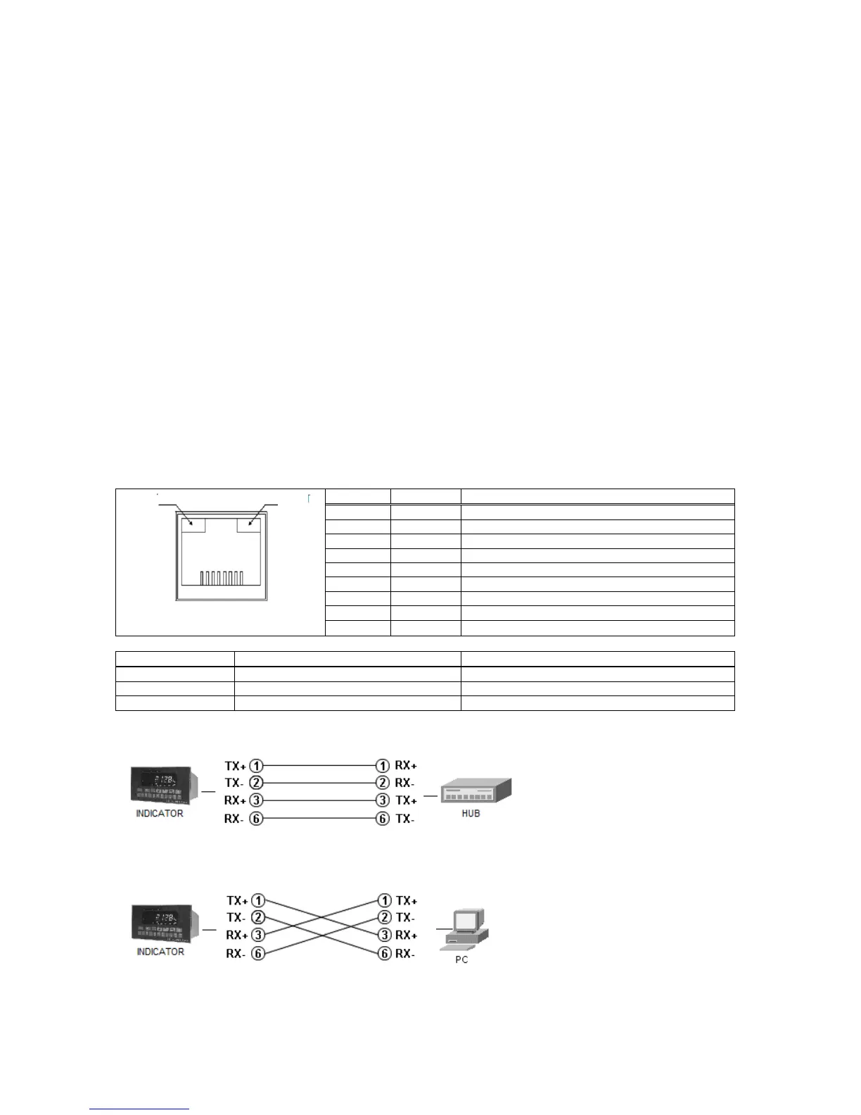
8.3.1 Electrical Connections
The pin configuration of the RJ45 Ethernet connector is described below:
1: Link LED
2 Activity LED
Differential Ethernet transmit data +
Differential Ethernet transmit data –
Differential Ethernet receive data +
Differential Ethernet receive data –
Connection to an Ethernet hub
Cabling is done using a standard
RJ-45 patch cable.
Direct connection to a PC
Cabling is done using a RJ-45
cross over cable.