4 – Installation
A6700sc/A6750sc User’s Manual
11
4 Installation
4.1 Basic Connections
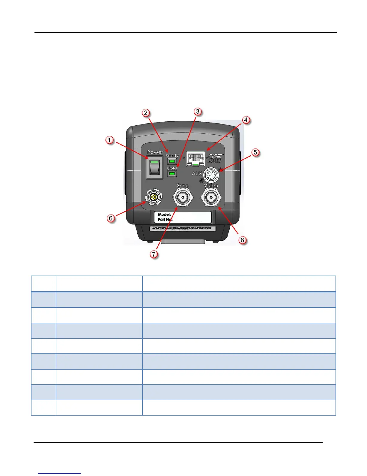
All connections to the A6700sc are located on the Back Panel.
Item Name Description
1
Power Switch LED will light when power is ON
2
Ready Light LED will turn on when camera is booted
3
Cold LED LED will light when FPA temp is <80K
4
Gigabit Ethernet (RJ45) Connect to a PC for digital IR image data
5
AUX Connector A675xsc only. (See Section 6.1.3.4 for details)
6
DC Power Input 24VDC
7
Sync Input External Frame Sync
8
Video Out NTSC or PAL, selectable in camera controller