6 – Interfaces
A6700sc/A6750sc User’s Manual
36
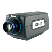
6.1.1 Status Lights
The A6700sc provides a set of status indicators on the back panel to give the user some visual
feedback on the camera operating state.
POWER (on power switch): Indicates that the camera is ON.
READY: Camera electronics have completed boot up. Camera is
ready to accept commands.
COLD: Indicates that the FPA has reached operating temperature
(<80K).
6.1.2 Power Interface
24V DC nominal, external AC-DC power converter is provided with the A6700sc camera system as a
standard accessory. Power supply specifications are:
Input voltage range: 100-250VAC 50/60Hz
Current draw: 24 VDC at up to 4.0 amps input to the camera
Converter dimensions: 6.25 inches x 3.5 inches x 2.75 inch (L x W x H)
Converter weight: approximately 1 lb
The power input pinouts are shown in Figure 6-4.
Figure 6-4: A6700sc Power Input Pinouts
When using your own DC power supply, you should take note of the following information:
Output voltage: 24 VDC
Current draw: 1.4 amps nominal steady state, 2.6 amps peak (during cooldown)
A6700sc power dissipation is <50 Watts steady state at nominal ambient temperature.
Mating Connector: Fisher Connectors, S103A052-130+E31 103.1/5.7 +B. (FLIR PN 26399-000).
The power cable should be 20AWG (stranded 10/30), 3 conductor, no shield, max diameter of 0.223
inches. (Example: Alphawire PN 882003)