427-0075-01-12 Version 110 November 2017 12
1 PT-Series HD Camera Installation
1.6.2 Connecting power
The camera itself does not have an on/off switch. Generally a circuit breaker will be used to apply or
remove power to the camera. If power is supplied to it, the camera will be in one of two modes: Booting
Up or Powered On.
The power cables supplied by the installer must use wires that are sufficient size gauge (16 AWG
recommended) for the supply voltage and length of the cable run. Always follow local building codes!
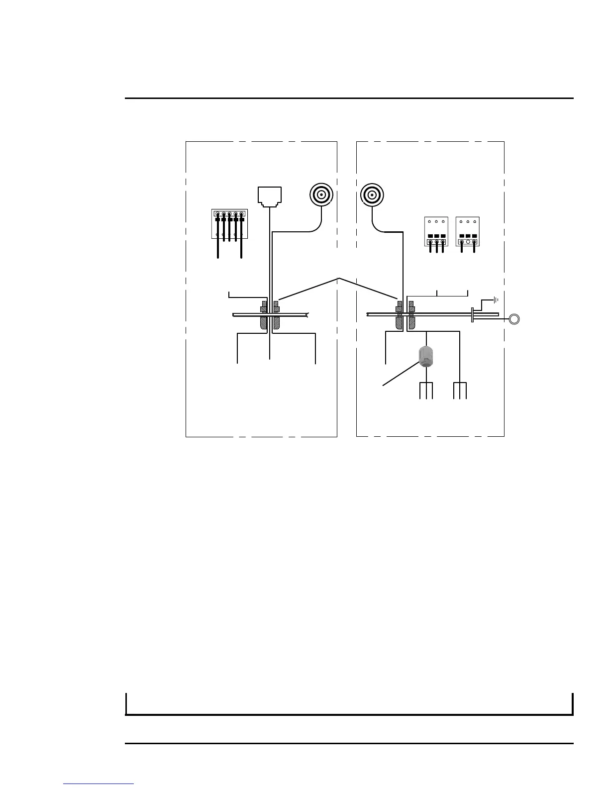
To satisfy FCC requirements, the supplied noise suppression ferrite must be installed on the camera
system power cable unless power cables are enclosed in metal conduit. Refer to
Figure 1-4.
Note that the heater power cable requires two-wire power. Do not connect to the power supply ground.
Ensure the camera is properly grounded. Typical to good grounding practices, the camera chassis
ground should be provided using the lowest resistance path possible. FLIR requires using a grounding
strap anchored to the grounding lug on the back plate of the camera housing and connected to the
nearest earth-grounding point.
Note
The terminal blocks for power connections will accept a maximum 16 AWG wire size.
Gland A Camera End
Serial and IP Communications
Main Analog Video
Gland B Camera End
Auxiliary Analog Video and Power
EthernetSerial
Control
Male
BNC
Video
Ethernet
RS232
RS422
20 AWG MAX
RX+
TX+
GND
RD(A)-
GND
RD(B)+
TD(A)-
TD(B)+
1
2
3
4
5
{
Main
Port
Back Cover
16 AWG Shielded
16 AWG Shielded
Local
GND
24
VAC/DC
24
VAC/DC
1
2
3
1
2
3
24 VAC/DC+
24 VAC/DC-
Earth Ground
24 VAC/DC+
24 VAC/DC-
{
{
Chassis
GND
Video
Male
BNC
Auxiliary
Port
Heater
Power
Camera
Power
Heater
Power
Camera
Power
3/4” NPT for Cable
Gland or Conduit
Noise suppression
ferrite (supplied)
Figure 1-5: PT-Series HD Camera Connection Schematic
 Loading...