427-0075-01-12 Version 110 November 2017 14
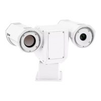
1 PT-Series HD Camera Installation
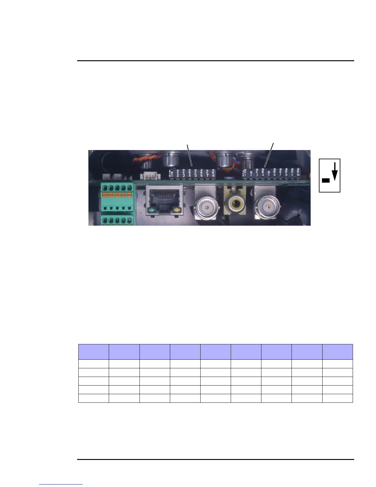
1.6.6 Serial Communications Settings - Hardware DIP Switches
The camera has two blocks of DIP switches that are used to configure the serial communications
settings. One block of switches has 8 switches and is used to set the serial address (or ID) of the
camera. The other block of switches has 10 switches and is used to set baud rate, hardware protocol
(RS-232 or RS-422), serial protocol (Pelco D or Bosch), and Software Override.
The figure below shows the locations of dip switches SW102 and SW103.
When the Software Override DIP switch is set to the Off position (as it is by default), all of the other DIP
switches will be ignored, and configuration changes must be made through software. If the switch is
set to the On position, all configuration settings related to serial communications are made with the
DIP switches, and changes that are made via software (with a web browser) will be ignored.
Serial Address: Use the block of switches on the left (SW102) to set the serial address of the
camera. The available range of values is from decimal 1 to 255. The dip switches are interpreted as a
binary number, with switch 1 representing the least significant bit (the switches are in the reverse order
of the bits). For convenience, a table of serial addresses and their binary equivalents is included at the
end of the manual. Refer to
Serial Address: Decimal To Binary Conversion, pg. 45
Table 1-2: Dip Switch Address/ID Settings—SW101
ID
Sw 1
LSB
Sw 2 Sw 3 Sw 4 Sw 5 Sw 6 Sw 7
Sw 8
MSB
1 On Off Off Off Off Off Off Off
2 Off On Off Off Off Off Off Off
3 On On Off Off Off Off Off Off
… … … … … … … … …
255 On On On On On On On On
Figure 1-6: PT-Series HD Serial Communications Configuration
SW102 SW103
Off
On
Switch
Position
 Loading...