REGULATION INSTRUCTIONS
29
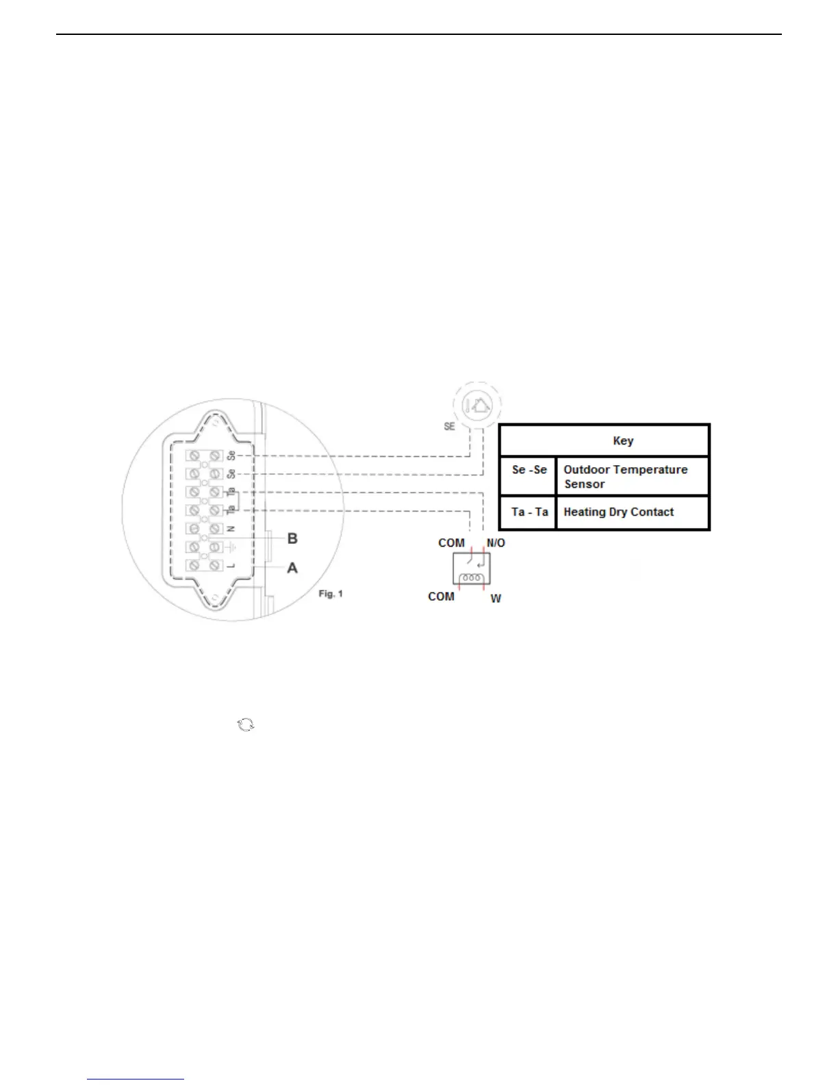
3.8.3 Remote control connection
Electrical connections (Option)
Connect the power supply to the terminal board located onto the control panel as
follows:
a.
switch off the power supply at the main switch;
b.
remove the front case panel of the boiler.(see paragraph '6.3 Accessing the boiler');
c.
Slacken the screws and remove plate A from the control panel (see fig. 1). With the plate removed, proceed
with the following wires connection:
•
of the outdoor temperature sensor on contacts marked as Se
·
Se on the terminal board "B";
• remove jumper from Ta –Ta from the terminal board B and install the control field supplied control wire
leading to a heating dry contact
d.
When wires have been connected, place plate "A" back to position and then the front case panel.
In case of a simultaneously outdoor temperature sensor and remote control installation, the printed circuit board
sends the outdoor temperature value to the remote control only, without using it for the modulation. The
communication between the printed circuit board and the remote control happens separately from the boiler
functioning mode selected and, once the connection has been established, the user interface on board is disabled
and displayed by the symbol
.