INSTALLATION INSTRUCTIONS
67
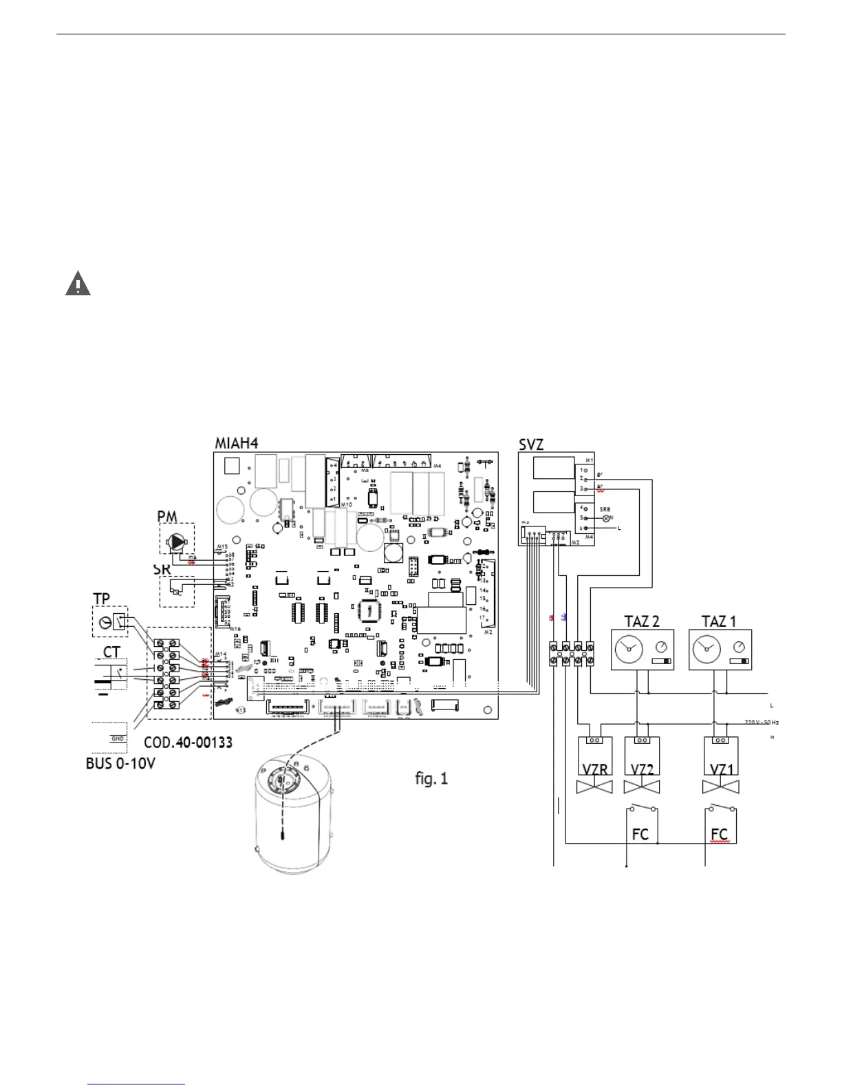
6.9 D.H.W. Sensor Connection
To wire the options below:
• (PM) MODULATING PUMP
• (TP) DOMESTIC HOT WATER PRE-HEATING DEACTIVATION TIMER
• (CT) TELEPHONE DIALER
• BUS 0-10V
• (SVZ) CONTROL BOARD FOR AREA VALVES CONNECTED TO A REMOTE CONTROL COD. 65- 00030
• (SB) DHW PROBE FOR REMOTE STORAGE CYLINDER - COD. 31368LA (MAX. LENGHT 8 m)use the
electronic board placed inside the control panel as follows:
DANGER
Cut off the voltage from the main switch.
• remove the water heater's front casing (refer to chapter ACCESSING THE WATER HEATER).
• remove the crankcase of the control panel (see chapter ACCESSING THE ELECTRONIC BOARD).
• after removing the crankcase, connect the items below to the electronic board (see fig. 1):
After performing these operations, remount the crankcase and the front casing.
REMOTE LED FOR SIGNALLING STORAGE CYLIN. BLOCK
ENVIRONMENT THERMOSTAT AREA 1
ENVIRONMENT THERMOSTAT AREA 2