REGULATION INSTRUCTIONS
40
Once the system has been filled, proceed as
follows:
• Check that the exhaust vent is free of
obstructions and correctly connected to the
water heater;
• Switch on the power supply to the water
heater;
• Open the gas isolation valve;
• Place switch 1 in the ON position (see 2.7 “Control Panel”), after a few seconds the circulating pump will start to
run;
• Use button 6 to set the SUMMER, WINTER or
SUMMER/WINTER function. The symbols
will light up (fixed light) to indicate that
the water heater is working;
• The automatic ignition system will then light
the burner. This operation is repeated for 3
times. It may however be necessary to repeat
the operation in order to eliminate all the air
from the pipes. To repeat the operation, wait
approximately three minutes before re-
attempting to light the water heater. To reset
the water heater Switch off switch 1 (see 2.7
“Control Panel”) and switch it back on again
and repeat the lighting procedure;
• With the water heater ignited, if the system still
emits noises, the operations must be repeated
until all the air has been removed;
• Check the pressure in the system. If the
pressure has fallen, re-open the filling tap until
the code H2O disappears on the display and
the pressure reaches the middle of the green
area (1,2 bar). On completion, close the
filling tap.
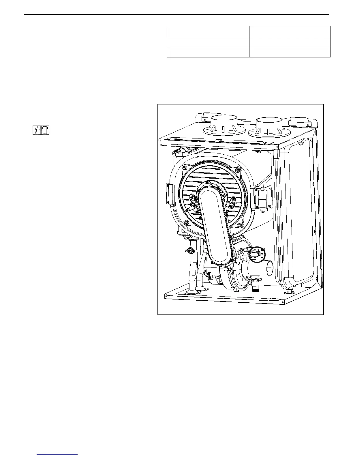
• If the CO2 value does not correspond to the
specified value, adjust screw V (see fig. 1) on
the venture clockwise to reduce the CO2 value
or anticlockwise to increase it
;
Liquid Propane Gas - G 31