CPX, CPXR, CPXN and CPXP USER INSTRUCTIONS ENGLISH 71569117 02-10
Page 23 of 44 flowserve.com
of a non-standard part) will invalidate the pump’s
safety certification.
6.3.2 Storage of spares
Spares should be stored in a clean dry area away
from vibration. Inspection and re-treatment of
metallic surfaces (if necessary) with preservative is
recommended at 6 monthly intervals.
6.4 Recommended spares
For two years operation (as per VDMA 24296).
Number of pumps
(including stand-by)
Part no.
Designation
2 3 4 5 6/7 8/9 10(+)
2200 Impeller 1 2 3 30%
2100 Shaft 1 2 3 30%
3712.1 Bearing locknut 1 2 3 4 50%
2400 Sleeve (if fitted) 2 3 4 50%
3011 Radial ball bearing 1 2 3 4 50%
3013 Thrust bearing 1 2 3 4 50%
4590.1 *
Gasket 4 6 8 9 12 150%
4610.1 O-ring 4 6 8 9 12 150%
4610.2 O-ring 4 6 8 9 10 100%
2540.2 Flinger 1 2 3 30%
4130 Gland packing 2 3 4 40%
4134 Lantern ring 1 2 3 30%
4200 Mechanical seals 1 2 3 30%
- Power end - - - - - 1 2
* Note: for CPXR replace with the following part:
4590.1 Gasket 8 12
16 18 24 300%
Additional spares for keyed impeller option
2912.1 /
2912.2
Impeller nut 1 2 3 30%
4610.4
O-ring
(if sleeve fitted)
2 3 4 50%
4610.5 O-ring 4 6 8 9 12 150%
6700.2 Key 1 2 3 30%
6.5 Tools required
A typical range of tools that will be required to
maintain these pumps is listed below.
Readily available in standard tool kits, and dependent
on pump size:
• Open ended spanners (wrenches) to suit up to
M 24 screws/nuts
• Socket spanners (wrenches), up to M 24 screws
• Allen keys, up to 10 mm (A/F)
• Range of screwdrivers
• Soft mallet
More specialized equipment:
• Bearing pullers
• Bearing induction heater
• Dial test indicator
• C-spanner (wrench) - for removing shaft nut.
(If difficulties in sourcing are encountered, consult
Flowserve.)
• Coupling grip/shaft spanner
6.6 Fastener torques
Fastener Screw size Torque Nm (lbf ft)
All except where
otherwise stated
M8
M10
M12
M16
M20
16 (12)
25 (18)
35 (26)
80 (59)
130 (96)
Impeller nut
M12
M16
M22
M24
16 (12)
41 (31)
106 (79)
135 (100)
Non-metallic gaskets incur creep
relaxation - before commissioning the pump check
and retighten fasteners to tightening torques stated.
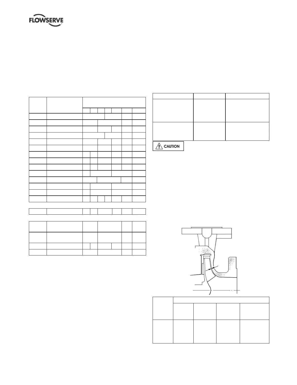
6.7 Setting impeller clearance
This procedure may be required after the pump has
been dismantled or a different clearance is required.
Before carrying out this procedure ensure that the
mechanical seal(s) [4200] fitted can tolerate a change
in their axial setting, otherwise it will be necessary to
dismantle the unit and reset the seal axial position
after adjusting the impeller clearance.
Clearance mm (in.)
Temp
ºC
(ºF)
Impellers
up to
210 mm
Impellers
211 mm to
260 mm
Impellers
over 260 mm
(except *)
(*)150CPX400
(*)200CPX400
(*)150CPX500
50 (122)
100 (212)
150 (302)
200 (392)
250 (482)
0.3 (0.012)
0.4 (0.016)
0.5 (0.020)
0.6 (0.024)
0.7 (0.028)
0.4 (0.016)
0.5 (0.020)
0.6 (0.024)
0.7 (0.028)
0.8 (0.032)
0.5 (0.020)
0.6 (0.024)
0.7 (0.028)
0.8 (0.032)
0.9 (0.036)
1.0 (0.040)
1.0 (0.040)
1.1 (0.044)
1.2 (0.048)
1.3 (0.052)