CPX, CPXR, CPXN and CPXP USER INSTRUCTIONS ENGLISH 71569117 02-10
Page 29 of 44 flowserve.com
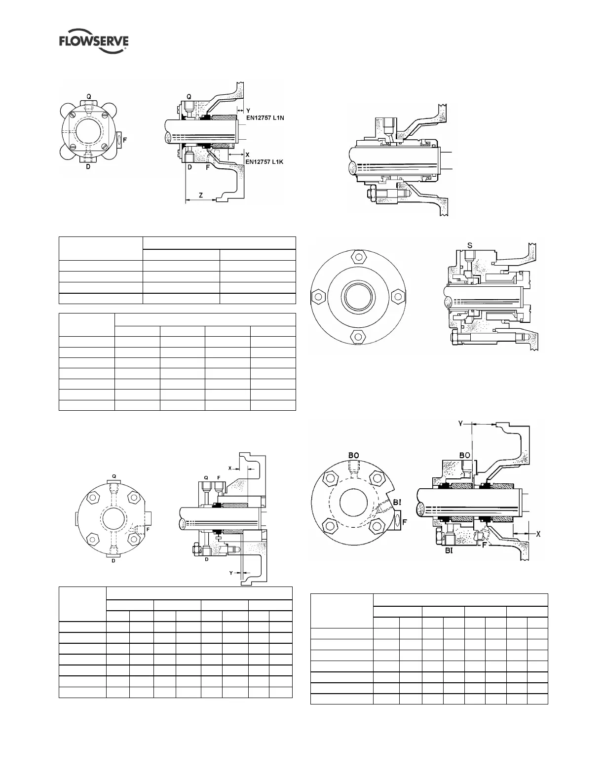
6.11.1d Single seal with external lip seal
NB: Lever flange away after fitting hard sleeve to shaft.
Setting dimension (mm)
Bearing housing
X Y
Frame 1 23.5 11.0
Frame 2 34.0 19.0
Frame 3 33.5 11.0
Frame 4 51.5 24.0
Setting dimension Z (mm)
Pump size
Frame 1 Frame 2 Frame 3 Frame 4
125 41.5 - - -
160 41.5 49.0 - -
200 36.5 49.0 - -
250 - 44.0 45.0 -
315 - 44.0 45.0 65.0
400 - - 36.5 57.0
500 - 44.0 45.0 65.0
6.11.1e Single internal seal with internal and
external neck bush
EN12757 L1N
EN12757 L1K
Setting dimensions (mm)
Frame 1 Frame 2 Frame 3 Frame 4
Pump
size
X Y X Y X Y X Y
125 12.5
0 - - - - - -
160 12.5
0 5.5 -9.5 - - - -
200 17.5
5.0 5.5 -9.5 - - - -
250 - - 10.6
-4.4 18.3
-4.3 - -
315 - - 10.6
-4.4 18.3
-4.3 -4.7
-32.3
400 - - - - 27.0
4.3 3.5 -24.0
500 - - 10.6
-4.4 18.3
-4.3 -4.7
-32.3
6.11.2 Cartridge seal types
6.11.2a Cartridge seal in conical cover
6.11.2b Hooked sleeve cartridge seal
For S see seal supplier's instructions.
6.11.3 Tandem seal types
6.11.3a Tandem seal with Flowserve eccentric
pumping annulus circulation
BI - Rp ¼ in. barrier liquid inlet
BO - Rp ¼ in. barrier liquid outlet
F - Rp ¼ in. flush
Setting dimensions (mm)
Frame 1 Frame 2 Frame 3 Frame 4
Pump
size
X Y X Y X Y X Y
125 20.0 31.5
- - - - - -
160 20.0 31.5
28.0
41.5
- - - -
200 20.0 26.5
28.0
41.5
- - - -
250 - - 28.0
36.4
27.5
33.7
- -
315 - - 28.0
36.4
27.5
33.7
45.5
56.7
400 - - - - 27.5
25.3
45.5
48.3
500 - - 28.0
36.4
27.5
33.7
45.5
56.7
Q - Rp ¼ in. quench
D - Rp ¼ in. drain
F - Rp ¼ in. flush
Z - Position of lip seal hard sleeve
Q - Rp ¼ in. quench
D - Rp ¼ in. drain
F - Rp ¼ in. flush